Inst ToolsInst ToolsInst Tools
  • Courses
  • Automation
    • PLC
    • Control System
    • Safety System
    • Communication
    • Fire & Gas System
  • Instrumentation
    • Design
    • Pressure
    • Temperature
    • Flow
    • Level
    • Vibration
    • Analyzer
    • Control Valve
    • Switch
    • Calibration
    • Erection & Commissioning
  • Interview
    • Instrumentation
    • Electrical
    • Electronics
    • Practical
  • Q&A
    • Instrumentation
    • Control System
    • Electrical
    • Electronics
    • Analog Electronics
    • Digital Electronics
    • Power Electronics
    • Microprocessor
  • Request
Search
  • Books
  • Software
  • Projects
  • Process
  • Tools
  • Basics
  • Formula
  • Power Plant
  • Root Cause Analysis
  • Electrical Basics
  • Animation
  • Standards
  • 4-20 mA Course
  • Siemens PLC Course
Reading: C-Bourdon Tube Pressure Gauge Theory
Share
Font ResizerAa
Inst ToolsInst Tools
Font ResizerAa
  • Courses
  • Design
  • PLC
  • Interview
  • Control System
Search
  • Courses
  • Automation
    • PLC
    • Control System
    • Safety System
    • Communication
    • Fire & Gas System
  • Instrumentation
    • Design
    • Pressure
    • Temperature
    • Flow
    • Level
    • Vibration
    • Analyzer
    • Control Valve
    • Switch
    • Calibration
    • Erection & Commissioning
  • Interview
    • Instrumentation
    • Electrical
    • Electronics
    • Practical
  • Q&A
    • Instrumentation
    • Control System
    • Electrical
    • Electronics
    • Analog Electronics
    • Digital Electronics
    • Power Electronics
    • Microprocessor
  • Request
Follow US
All rights reserved. Reproduction in whole or in part without written permission is prohibited.
Inst Tools > Blog > Pressure Measurement > C-Bourdon Tube Pressure Gauge Theory

C-Bourdon Tube Pressure Gauge Theory

Last updated: December 22, 2018 1:24 am
Editorial Staff
Pressure Measurement
No Comments
Share
3 Min Read
SHARE

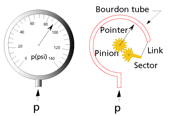
The Bourdon tube works on a simple principle that a bent tube will change its shape when exposed to variations of internal and external pressure. As pressure is applied internally, the tube straightens and returns to its original form when the pressure is released.

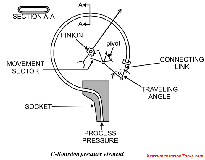
The tip of the tube moves with the internal pressure change and is easily converted with a pointer onto a scale. A connector link is used to transfer the tip movement to the geared movement sector. The pointer is rotated through a toothed pinion by the geared sector.

This type of gauge may require vertical mounting (orientation dependent) for correct results. The element is subject to shock and vibration, which is also due to the mass of the tube. Because of this and the amount of movement with this type of sensing, they are prone to breakage, particularly at the base of the tube.

C-Bourdon Tube

The main advantage with the Bourdon tube is that it has a wide operating (depending on the tube material). This type of pressure measurement can be used for positive or negative pressure ranges, although the accuracy is impaired when in a vacuum.

Also See: Bourdon Tube Animation

Selection and Sizing

The type of duty is one of the main selection criteria when choosing Bourdon tubes for pressure measurement. For applications which have rapid cycling of the process pressure, such in ON/OFF controlled systems, then the measuring transducer requires an internal snubber. They are also prone to failure in these applications.

Liquid filled devices are one way to reduce the wear and tear on the tube element.

Advantages

  • Inexpensive
  • Wide operating range
  • Fast response
  • Good sensitivity
  • Direct pressure measurement

Disadvantages

  • Primarily intended for indication only
  • Non linear transducer, linearised by gear mechanism
  • Hysteresis on cycling
  • Sensitive to temperature variations
  • Limited life when subject to shock and vibration

Application Limitations

These devices should be used in air if calibrated for air, and in liquid if calibrated for liquid. Special care is required for liquid applications in bleeding air from the liquid lines.

This type of pressure measurement is limited in applications where there is input shock (a sudden surge of pressure), and in fast moving processes.

If the application is for the use of oxygen, then the device cannot be calibrated using oil. Lower ranges are usually calibrated in air. Higher ranges, usually 1000kPa, are calibrated with a dead weight tester (hydraulic oil).

Don't Miss Our Updates
Be the first to get exclusive content straight to your email.
We promise not to spam you. You can unsubscribe at any time.
Invalid email address
You've successfully subscribed !

Continue Reading

Differential Pressure Sensors Calibration Procedure
Types of Bourdon Tube
Pressure Gauges with Diaphragm Sensor Principle
Pressure Gauge Calibration according to Standard DKD-R-6-1
Difference between Absolute, Gauge and Differential Pressure Transmitters
Pressure Transmitter Vent fittings
Share This Article
Facebook Whatsapp Whatsapp LinkedIn Copy Link
Share
Leave a Comment

Leave a Reply Cancel reply

Your email address will not be published. Required fields are marked *

Stay Connected

128.3kFollowersLike
69.1kFollowersFollow
210kSubscribersSubscribe
38kFollowersFollow

Categories

Explore More

Top 30 Interview Questions on Pressure Measuring Devices
All About Instrumentation Impulse Lines
Pressure Transmitter Circuit
Temperature Compensation for Pressure Measurement
Pressure Transmitter Applications
Pressure Transmitters Purged impulse lines
Identify the Pressure Gauge Error
Diaphragms

Keep Learning

pressure-gauge-animation

Bourdon Tube Pressure Gauge Working Principle Animation

Impulse Line Pressure Testing Procedure

Impulse Line Pressure Testing Procedure

Compression load cell Principle

Types of Load Cells

The Principle of Dead Weight Pressure Tester

The Principle of Dead Weight Pressure Tester

pressure gauge snubber

Pressure Gauge Snubbers

5 Valve manifold

5 Valve Manifold Operation

Differential Pressure Flow Transmitter Interview Questions

Interview Questions on Differential Pressure Flow Transmitter

Differential Pressure Transmitter Question

Differential Pressure Transmitter Questions

Learn More

Instrument Calibration Questions

Instrument Calibration Questions

Types of MCB

Types of MCB

Identification of Equipment Standards

Identification of Equipment

Ultrasonic Flowmeters Principle

Factors Affecting the Performance of Ultrasonic Flow Meters

Control Valve in Last Position

Control Valve Fail Safe Action

Introduction to SCADA

PLC Program for Conveyor Motor

PLC Conveyor Motor Ladder Logic

ATEX Standards

ATEX Standards

Menu

  • About
  • Privacy Policy
  • Copyright

Quick Links

  • Learn PLC
  • Helping Hand
  • Part Time Job

YouTube Subscribe

Follow US
All rights reserved. Reproduction in whole or in part without written permission is prohibited.
Welcome Back!

Sign in to your account

Username or Email Address
Password

Lost your password?