Electrical Transformer is the most used electrical machine in power system. Both in the power transmission and distribution of ac network, transformer has its mandatory use.
1. Basics of electrical transformer
1. What is electrical transformer
Transformer is an electrical machine that transfers unchanged electrical energy and frequency with a modification of voltage and current between two circuits or more than two circuits.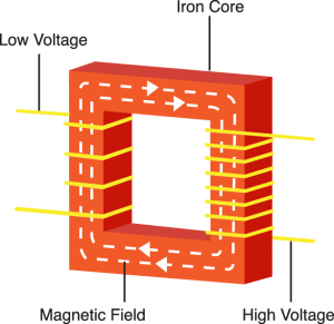
So transformer –
- Does not modify the power between primary and secondary.
- Does not modify the frequency of AC current or voltage.
- Only modify the voltage and current.
2. List of international standard for transformer
- IEC 60076-8 Power transformers –Application guide. IEC (International Electrotechnical Commission).
- IEC 60050(421):1990, International Electrotechnical Vocabulary (IEV) – Chapter 421: Power transformers and reactors
- IEC 60354:1991, Loading guide for oil-immersed power transformers
- IEC 60722:1982, Guide to the lightning impulse and switching impulse testing of power transformers and reactors.
- IEC 60905:1987, Loading guide for dry-type power transformers.
- IEC 61378-1: 1997, Convertor transformers – Part 1: Transformers for industrial applications
3. Use of electrical transformer
1. To change the voltage and current level: Modern ac transmission technology requires the voltage to be higher such as 11KV, 33KV, 133Kv, 232KV. This is required to minimize the transmission loss and making the transmission line lighter, thinner hence less copper is needed. On the other hand consumer end voltage level is 400, 200, 120 etc. Transformer is used to step up or step down the voltage level. Also potential transformer is used in some protection and measurements purposes. . To change the current level- Changing current level is required in some protection and measurement instruments named is current transformer.
2. To provide galvanic isolation: Some transformer is used to isolate two circuits (no physical connection) but maintain the energy transfer by electromagnetic induction. This way both circuit can be safe from each other also different potential can be maintained.
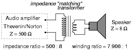
3. To provide impedance matching : Power is unchanged in transformer primary and secondary, only voltage and current is changed. These can be used to convert the impedance of a load to a different level. R=V/I, now say V=200, I=10 then R=20ohm; and for V=100, I=20 then R=5ohm. In both cases the power is same 2000Watt but impedance is varied. As per Maximum Power Transfer Theorem maximum power is transferred when impedance is matching. Thus impedance matching mostly used in audio system where impedance of speaker and phone are of mismatch.
4. Types of Electrical transformer
By voltage change
- Step Up- Increases the secondary voltage and thus the secondary current is decreased.
- Step down- Decreases the secondary voltage and thus secondary current is increased.
By application
- Power transformer- used in between the power plant (power generation) up to the distribution network. Specially designed to withstand higher stress & faults in the transmission and generation network.
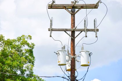
- Distribution transformer – Used in the primary or secondary distribution network. As it is in the consumer end -specially designed for continuous service, variable load demand.
- Phase shifting transformer- to control the amount flow of active power between two transmission lines.
- Traction type transformer- Transformer used in the electric rail services to supply electric power to the rail or tram from the overhead electrical power cable.
- Rectifier transformer or HVDC (High voltage DC transformer) – This types of power transformer is used in high voltage DC network where there is AC network. HVDC transformer is the combination of (a) regular transformer + rectifier circuit(to convert AC to DC) in primary or secondary ; or (b)regular transformer + inverter circuit( to convert DC to AC ) in primary or secondary.
By types of cooling
- Liquid type – Transformer oil is used as a di-electric medium and also as a cooling medium. The transformer core is submerged in the transformer oil. This types of transformer is of low cost with a disadvantage of environmental impact (transformer oil is not environment friendly) and possibility of fire hazard.
- Dry type transformer-Aluminum and resin is used as the structural material in dry type transformer. Both these material has high di-electric strength and also self-cooling property. To minimize environmental contamination and fire hazard, customers are specifying dry-type transformers more frequently. Also there is less space required, less civil work is needed. Dry type transformers are costly.
2. Electrical Transformer theory and concepts
1. How transformer works
Transformer as a static device uses the electromagnetic induction principle of Faradays’ Law of Electromagnetic induction. In this case there are no movement to get the relative motion between the constant flux and the conductor. Instead in transformer the flux is not fixed or constant but varying to get the relative effect.
Transformer transfers energy from primary to secondary through electromagnetic induction. These primary and secondary windings are coupled by mutual magnetic flux. The essence of transformer action requires only the existence of time-varying mutual flux linking two windings.
An alternating voltage is connected to the primary coil. These create flux in the coil. As the voltage is alternating or time varying so is the produced flux. These time-varying flux produces induced voltage in the secondary winding when it cuts through the secondary coil or winding.
- Transformer works on the theory of Faraday’s Laws of electromagnetic induction.
- The main important factor is to maintaining controlled difference between the number of primary turn and secondary turn.
2. How Energy is transferred from primary winding to secondary winding in transformer
The net energy transferred is same for primary circuit and secondary circuit (discarding the losses and considering that all the primary magnetic flux are associated with the secondary circuit.).
Both the primary power and secondary power in transformer is same, all is varied is the primary & secondary – voltage and current. Also other parameters like frequency is remain unchanged between primary and secondary windings.
3. Transformer formula
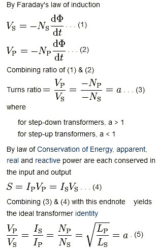
Vs= Secondary voltage, Is=secondary current, Ns=number secondary turn.
(Np/Ns)=(Vp/Vs)=(Is/Ip)
4. How the voltage and current is changed between the primary and secondary
The change in voltage from primary to secondary is done by the number of coil turns variation in primary and secondary.
As transformer works on the Faraday’s law of induction, we can describe voltage and current change in transformer by following manner.
First we consider that all the flux from primary circuit is involve in the secondary circuit. That is there is no loss of magnetic flux, which is the case in reality for modern design of transformer.
1. Change in voltage Now as the magnetic flux is constant what left from the Faraday’s formula is the number of turn (N) and voltage (V). The relation is “voltage varies proportionally with the number of turns. “ So increase the number of turns, voltage will be increased. Decreased the number of turns voltage will be decreased.
2. Change in current As per Voltage and current relation, voltage and current are inversely related. If voltage is increased then the current will be decreased and vice versa.
By properly proportioning the number of primary and secondary turns, almost any desired voltage ratio, or ratio of transformation, can be obtained.
Transformer construction
1. Basic construction of transformer
A basic transformer has simplest construction with primary winding set, secondary winding set and core. Core is the medium for passing the magnetic flux from primary winding to secondary winding. Generally iron core is used because it has higher permeability for magnetic flux. It means heat transfers better in iron then in wood and same as magnetic flux transfers or passes better in iron core then the air.
2. Why there is iron core instead of air core in transformer
Time-varying mutual flux links the both primary and secondary winding in transformer. It is required that most of the flux is to be confined to a definite, high-permeability path linking the windings. Now with air ore it is not possible but with core of iron or other ferromagnetic material coupling is effectively done. Because most of the flux in iron core is confined to a definite, high-permeability path linking the winding.
3. Iron core in transformer-
As the iron core is also under the flux variation in transformer there is some voltage induced in the iron core. This voltage is called the eddy voltage and in result there is a current named eddy current flow in the iron core. These results in heating up the core. With a solid iron core the eddy current is high.
To avoid this solid iron core is not used. Thin iron core is laminated to make it non-conductive. Then this thin laminated core is stacked by several to get the complete iron core structure. With this modification eddy current is reduced but magnetic property of the iron core is remained unchanged.
4. Materials of iron core of transformer-
- Silicon steel for low cost, low core loss, and high permeability at high flux densities (1.0 to 1.5 T).
- Compressed powdered ferromagnetic alloys known as ferrites- used in the core of small transformer used in communication circuits at high frequencies and low energy levels.