Inst ToolsInst ToolsInst Tools
  • Ask
  • Courses
  • Videos
  • Q & A
    • Interview
      • Instrumentation
      • Electronics
      • Electrical
      • Practical Questions
    • MCQ
      • Instrumentation MCQ
      • Electrical MCQ
      • Electronics MCQ
      • Control Systems MCQ
      • Analog Electronics MCQ
      • Digital Electronics MCQ
      • Power Electronics MCQ
      • Microprocessor MCQ
      • Multiple Choice Questions
  • EE
    • Electronics
      • Electronics Q & A
      • Electronic Basics
      • Electronic Devices & Circuits
      • Electronics Animation
      • Digital Electronics
    • Electrical
      • Electrical Basics
      • Electrical Q & A
      • Power Electronics
      • Electrical Machines
      • Electrical Animation
      • Power Systems
      • Switchgear & Protection
      • Transmission & Distribution
  • Measure
    • Control Valves
    • Calibration
    • Temperature
    • Pressure
    • Flow
    • Level
    • Analyzers
    • Switches
    • Vibration
    • Solenoid Valve
  • Control
    • PLC Tutorials
    • Control Systems
    • Safety Instrumented System (SIS)
    • Communication
    • Fire & Gas System
  • More
    • Design
    • Tools
    • Animation
    • Basics
    • Formulas
    • Standards
    • TextBooks
    • Common
    • Software
    • Excel Tools
    • Erection & Commissioning
    • Process Fundamentals
    • Videos
    • Books
Search
All rights reserved. Reproduction in whole or in part without written permission is prohibited.
Reading: ISA codes for Process Instrumentation
Share
Notification Show More
Font ResizerAa
Inst ToolsInst Tools
Font ResizerAa
  • Courses
  • PLC Tutorials
  • Control Systems
Search
  • Ask
  • Courses
  • Videos
  • Q & A
    • Interview
    • MCQ
  • EE
    • Electronics
    • Electrical
  • Measure
    • Control Valves
    • Calibration
    • Temperature
    • Pressure
    • Flow
    • Level
    • Analyzers
    • Switches
    • Vibration
    • Solenoid Valve
  • Control
    • PLC Tutorials
    • Control Systems
    • Safety Instrumented System (SIS)
    • Communication
    • Fire & Gas System
  • More
    • Design
    • Tools
    • Animation
    • Basics
    • Formulas
    • Standards
    • TextBooks
    • Common
    • Software
    • Excel Tools
    • Erection & Commissioning
    • Process Fundamentals
    • Videos
    • Books
Follow US
All rights reserved. Reproduction in whole or in part without written permission is prohibited.
Inst Tools > Blog > Standards > ISA codes for Process Instrumentation

ISA codes for Process Instrumentation

Last updated: March 8, 2017 7:39 pm
Editorial Staff
Standards
1 Comment
Share
3 Min Read
SHARE

It is common to make letter combinations in PI&D diagrams according ANSI/ISA S5.1-1984 (R 1992) “Instrumentation symbols and identification”standard. In addition to the letter combination it is common with a succeeding number as a unique identification of the actual instrument. The numbering practice varies – some use a sequential number, others use a number related to the process line number or similar.

The below tutorial guides us about instrument tagplate assignment as per ISA standard

First Letter

First letter indicates a measured or initiating variable, or a modifier, such as Current (I), Speed (S) or Flow (F).

Measured or Initiating Variable

A – Analysis

B – Burner, combustion

C – User’s choice

D – User’s choice

E – Voltage

F – Flow rate

G- User’s choice

H – Hand

I – Current (electrical)

J – Power

K – Time, time schedule

L – Level

M- User’s choice

N- User’s choice

O- User’s choice

P – Pressure, vacuum

Q – Quantity

R – Radiation

S – Speed, frequency

T – Temperature

U – Multivariable

V – Vibration, mechanical analyses

W – Weight, force

X – Unclassified

Y – Event, state or presence

Z – Position, dimension

Modifier

D – Differential

F – Ration (fraction)

J – Scan

K – Time rate of change

M – Momentary

Q – Integrate, totalizer

S – Safety

X – X-axis

Y – Y-axis

Z – Z-axis

Second or Succeeding Letters

Second or succeeding letters indicates a readout or passive function, output function or a modifier function.

Readout or Passive Function

A – Alarm

B – User’s choice

E – Sensor (primary element)

G- Glass, viewing device

I – Indication

L – Light

N- User’s choice

O- Orifice, restriction

P – Point (test connection)

R – Record

U – Multifunction

W – Well

X – Unclassified

Output Function

B – User’s choice

C – Control

K – Control Station

N- User’s choice

S – Switch

T – Transmit

U – Multifunction

V – Valve, damper, louver

X – Unclassified

Y – Relay, compute, convert

Z – Driver, actuator

Modifier Function

B – User’s choice

H – High

L – Low

M – Middle, intermediate

N- User’s choice

U – Multifunction

X – Unclassified

Examples – P&ID codes

1.Flowmeter – Indicating

FI 001

2.Temperature – Transmitter

TT 001

3.Control Valve

FV 001

4.Position Switch – High Level

ZSH 001

Also Read: List of Instrumentation Standards

Don't Miss Our Updates
Be the first to get exclusive content straight to your email.
We promise not to spam you. You can unsubscribe at any time.
Invalid email address
You've successfully subscribed !
Hazardous Area Classification Questions
Instrumentation Standards Questions and Answers
Basics of Electromagnetic compatibility (EMC)
What is IEC 61508 ?
Understanding Hazardous Area Classification
Share This Article
Facebook Whatsapp Whatsapp LinkedIn Copy Link
Share
1 Comment
  • shakil akhtar says:
    February 6, 2016 at 2:03 pm

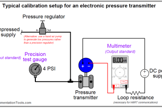
    Callibration procedure of TT,PT,FT & LT with HART? and its diagram.

    Reply

Leave a Reply Cancel reply

Your email address will not be published. Required fields are marked *

Stay Connected

128.3kFollowersLike
69.1kFollowersFollow
208kSubscribersSubscribe
38kFollowersFollow

Categories

Recent Comments

  • Kamli on Top Free PLC Software
  • Guifty Shimica on Top Non-PLC Certification Courses for Automation Professionals
  • Guifty Shimica on Top Non-PLC Certification Courses for Automation Professionals
  • MIHARITSOA Aina Sitraka on Top Non-PLC Certification Courses for Automation Professionals

Related Articles

ATEX Ratings, Intrinsic Safety, Hazardous Areas and Explosive Atmospheres

ATEX Ratings, Intrinsic Safety, Hazardous Areas and Explosive Atmospheres

Basics of Explosion Protection

Basics of Explosion Protection

Flammable Gases and Vapors Class 1 & Class 2

Gas Detectors Standards

Interview Questions & Answers on Alternators

Instrumentation Engineering Standards Questions & Answers

Intrinsic Safety Zones

Intrinsic Safety Protection ia and ib

Transmitters 4-20mA Current Failure Alarm Limits

Transmitters 4-20mA Current Failure Alarm Limits

Ingress Protection Standard

Ingress Protection Rating

Nameplate Markings

Explosive Atmospheres & Hazardous Classification

More Articles

Simatic Hardware Configuration

Configuration of Profibus Network in Siemens PLC

Manual Call Point Operating Principle

What is Manual Call Point (MCP) ?

MEASURING AN NPT CONNECTION

NPT Connection Measurement Size

Mitsubishi PLC Programming Tutorials

Switched Mode Power Supply (SMPS)

How does SMPS Works? – Switched Mode Power Supply

Mechanical Strainers

Strainers

Industrial Automation Cold and Hot Standby

Difference between Cold Standby and Hot Standby

PLC Ladder Diagram program

Contacts and Coils in PLC Ladder Logic

Follow US
All rights reserved. Reproduction in whole or in part without written permission is prohibited.
Welcome Back!

Sign in to your account

Username or Email Address
Password

Lost your password?