Inst ToolsInst ToolsInst Tools
  • Courses
  • Videos
  • Q & A
    • Interview
      • Instrumentation
      • Electronics
      • Electrical
      • Practical Questions
    • MCQ
      • Instrumentation MCQ
      • Electrical MCQ
      • Electronics MCQ
      • Control Systems MCQ
      • Analog Electronics MCQ
      • Digital Electronics MCQ
      • Power Electronics MCQ
      • Microprocessor MCQ
      • Multiple Choice Questions
  • EE
    • Electronics
      • Electronics Q & A
      • Electronic Basics
      • Electronic Devices & Circuits
      • Electronics Animation
      • Digital Electronics
    • Electrical
      • Electrical Basics
      • Electrical Q & A
      • Power Electronics
      • Electrical Machines
      • Electrical Animation
      • Power Systems
      • Switchgear & Protection
      • Transmission & Distribution
  • Measure
    • Control Valves
    • Calibration
    • Temperature
    • Pressure
    • Flow
    • Level
    • Analyzers
    • Switches
    • Vibration
    • Solenoid Valve
  • Control
    • PLC Tutorials
    • Control Systems
    • Safety Instrumented System (SIS)
    • Communication
    • Fire & Gas System
  • More
    • Design
    • Tools
    • Animation
    • Basics
    • Formulas
    • Standards
    • TextBooks
    • Common
    • Software
    • Excel Tools
    • Erection & Commissioning
    • Process Fundamentals
    • Videos
    • Books
Search
All rights reserved. Reproduction in whole or in part without written permission is prohibited.
Reading: Bipolar Junction Transistor Construction
Share
Notification Show More
Font ResizerAa
Inst ToolsInst Tools
Font ResizerAa
  • Courses
  • PLC Tutorials
  • Control Systems
Search
  • Courses
  • Videos
  • Q & A
    • Interview
    • MCQ
  • EE
    • Electronics
    • Electrical
  • Measure
    • Control Valves
    • Calibration
    • Temperature
    • Pressure
    • Flow
    • Level
    • Analyzers
    • Switches
    • Vibration
    • Solenoid Valve
  • Control
    • PLC Tutorials
    • Control Systems
    • Safety Instrumented System (SIS)
    • Communication
    • Fire & Gas System
  • More
    • Design
    • Tools
    • Animation
    • Basics
    • Formulas
    • Standards
    • TextBooks
    • Common
    • Software
    • Excel Tools
    • Erection & Commissioning
    • Process Fundamentals
    • Videos
    • Books
Follow US
All rights reserved. Reproduction in whole or in part without written permission is prohibited.
Inst Tools > Blog > Electronic Devices & Circuits > Bipolar Junction Transistor Construction

Bipolar Junction Transistor Construction

Last updated: September 27, 2016 4:17 pm
Editorial Staff
Electronic Devices & Circuits
No Comments
Share
2 Min Read
SHARE

The basic structure of the bipolar junction transistor (BJT) determines its operating characteristics.

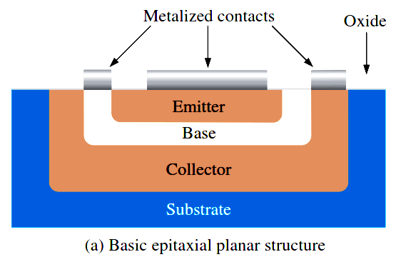
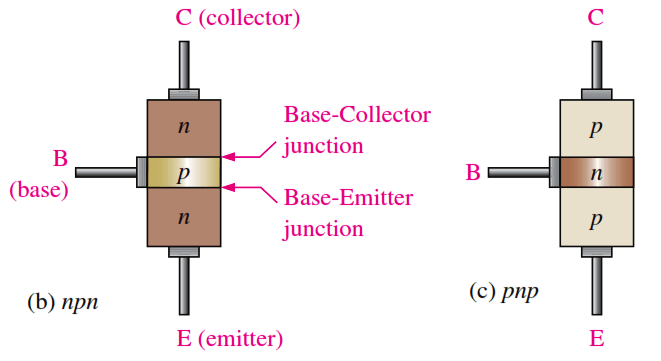
The BJT is constructed with three doped semiconductor regions separated by two pn junctions, as shown in the epitaxial planar structure in Figure (a). The three regions are called emitter, base, and collector. Physical representations of the two types of BJTs are shown in Figure (b) and (c). One type consists of two n regions separated by a p region (npn), and the other type consists of two p regions separated by an n region (pnp). The term bipolar refers to the use of both holes and electrons as current carriers in the transistor structure.
Bipolar Junction Transistor Construction

Fig : Basic BJT construction.

The pn junction joining the base region and the emitter region is called the base-emitter junction. The pn junction joining the base region and the collector region is called the base-collector junction, as indicated in Above Figure (b). A wire lead connects to each of the three regions, as shown. These leads are labeled E, B, and C for emitter, base, and collector, respectively.

bipolar-junction-transistor-symbol

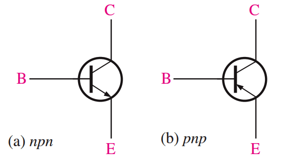
The base region is lightly doped and very thin compared to the heavily doped emitter and the moderately doped collector regions. The Below  Figure shows the schematic symbols for the npn and pnp bipolar junction transistors.
bjt-bipolar-junction-transistor-symbols

Don't Miss Our Updates
Be the first to get exclusive content straight to your email.
We promise not to spam you. You can unsubscribe at any time.
Invalid email address
You've successfully subscribed !

Continue Reading

Combining Independent Current Sources in Parallel
Short Circuit and Open Circuit
Resistors Principle & Applications
Full Wave Bridge Rectifier Peak Inverse Voltage
Insulators, Conductors and Semiconductors
Power MOSFET Safe Operating Area
Share This Article
Facebook Whatsapp Whatsapp LinkedIn Copy Link
Share
Leave a Comment

Leave a Reply Cancel reply

Your email address will not be published. Required fields are marked *

Stay Connected

128.3kFollowersLike
69.1kFollowersFollow
208kSubscribersSubscribe
38kFollowersFollow

Categories

Explore More

Half Wave Rectifier Principle
Transistors Questions & Answers
How a PN Junction Formed in a Diode
Classification of Bridge Circuits
Band Gap for Semiconductor Materials
Basic Transistor Amplifier Circuit Principle
Time Base Generator
Full Wave Bridge Rectifier Operation
Optoisolator Working Principle
Laser Diode Working Principle

Keep Learning

diode-basic-structure-symbol

Forward Bias & Reverse Bias of a Diode

transistor-terminals

Basics of Transistors

Transistor as Amplifier

Transistor as Amplifier

Testing a defective transistor

Testing a Transistor with a Digital Multimeter

temperature compensation circuit for PMMC

PMMC Temperature Compensation

Types-of-diodes

Different Types of Diodes

Short Notes on Rectifiers & Filters

Short Notes on Rectifiers & Filters

Fluorescent Screen of CRT

CRT Fluorescent Screen

Discover More

COCO Simulator

COCO Simulator: Free Process Simulation Software

PLC control 4 machines with 1 button

CX-Programmer Tutorial: 1 Button To Activate 4 Different Machines

PLC Instruction List Example for Level Control of Tank

PLC Instruction List Example for Level Control of Tank

DC motor speed control

DC Motor Speed Control

Simple Loop with Local Indication

Instrument Loop Test Requirements and Operation Procedures

Fuse in a Electrical Circuit

Advantages & Disadvantages of Fuse in a Electrical Circuit

trip solenoid installed on a control valve appears

SIS Final Control Elements

Sequencer Output in PLC

PLC Sequencer Instruction with Example

Follow US
All rights reserved. Reproduction in whole or in part without written permission is prohibited.
Welcome Back!

Sign in to your account

Username or Email Address
Password

Lost your password?