Inst ToolsInst ToolsInst Tools
  • Courses
  • Videos
  • Q & A
    • Interview
      • Instrumentation
      • Electronics
      • Electrical
      • Practical Questions
    • MCQ
      • Instrumentation MCQ
      • Electrical MCQ
      • Electronics MCQ
      • Control Systems MCQ
      • Analog Electronics MCQ
      • Digital Electronics MCQ
      • Power Electronics MCQ
      • Microprocessor MCQ
      • Multiple Choice Questions
  • EE
    • Electronics
      • Electronics Q & A
      • Electronic Basics
      • Electronic Devices & Circuits
      • Electronics Animation
      • Digital Electronics
    • Electrical
      • Electrical Basics
      • Electrical Q & A
      • Power Electronics
      • Electrical Machines
      • Electrical Animation
      • Power Systems
      • Switchgear & Protection
      • Transmission & Distribution
  • Measure
    • Control Valves
    • Calibration
    • Temperature
    • Pressure
    • Flow
    • Level
    • Analyzers
    • Switches
    • Vibration
    • Solenoid Valve
  • Control
    • PLC Tutorials
    • Control Systems
    • Safety Instrumented System (SIS)
    • Communication
    • Fire & Gas System
  • More
    • Design
    • Tools
    • Animation
    • Basics
    • Formulas
    • Standards
    • TextBooks
    • Common
    • Software
    • Excel Tools
    • Erection & Commissioning
    • Process Fundamentals
    • Videos
    • Books
Search
All rights reserved. Reproduction in whole or in part without written permission is prohibited.
Reading: Power MOSFET Safe Operating Area
Share
Notification Show More
Font ResizerAa
Inst ToolsInst Tools
Font ResizerAa
  • Courses
  • PLC Tutorials
  • Control Systems
Search
  • Courses
  • Videos
  • Q & A
    • Interview
    • MCQ
  • EE
    • Electronics
    • Electrical
  • Measure
    • Control Valves
    • Calibration
    • Temperature
    • Pressure
    • Flow
    • Level
    • Analyzers
    • Switches
    • Vibration
    • Solenoid Valve
  • Control
    • PLC Tutorials
    • Control Systems
    • Safety Instrumented System (SIS)
    • Communication
    • Fire & Gas System
  • More
    • Design
    • Tools
    • Animation
    • Basics
    • Formulas
    • Standards
    • TextBooks
    • Common
    • Software
    • Excel Tools
    • Erection & Commissioning
    • Process Fundamentals
    • Videos
    • Books
Follow US
All rights reserved. Reproduction in whole or in part without written permission is prohibited.
Inst Tools > Blog > Electronic Devices & Circuits > Power MOSFET Safe Operating Area

Power MOSFET Safe Operating Area

Last updated: October 6, 2016 7:36 am
Editorial Staff
Electronic Devices & Circuits
No Comments
Share
4 Min Read
SHARE

The safe operating area determines the current and voltage boundary within which the device can be operated without destructive failure.

There are two SOAs:

Forward Biased Safe Operating Area (FBSOA)
Reverse Biased Safe Operating Area (RBSOA)

It is recommended to read about power MOSFET structure for proper understanding of the Power MOSFET Safe Operating Area.

Some of the facts about Power MOSFET is given below:

  1. Power MOSFET has three terminals called Drain, Source and Gate.
  2. It is a voltage controlled device.
  3. It is a unipolar device so its operation depends upon the flow of majority carriers only.
  4. The gate circuit impedance very high.
  5. So the control signal(gate voltage) required to turn on the MOSFET is lesser than required control signal for the BJT.
  6. There is no second breakdown problem in this device.
  7. MOSFET has positive temperature coefficient, so thermal runaway problem will not happen.

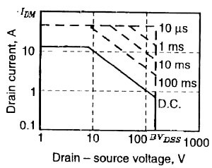
The Safe Operating Area of Power MOSFET is given here:

  • All the maximum voltage and current ratings and power dissipation are conveniently brought together in the safe operating area diagram.
  • This is based on logarithmic plot of drain current against Drain-to-Source voltage as shown in the figure.
  • The solid line shows the bounding values for DC operation.
  • When the MOSFET is operating for a short intervals, the power dissipation is lesser than the continuous operation.
  • So the Power MOSFET Safe Operating Area may be extended as shown in the figure by the dotted line.
  • The factors that determine the SOA of the Power MOSFET arePower MOSFET Safe Operating Area
    1. The maximum drain current IDM
    2. The breakdown voltage BVDSS
    3. The internal junction temperature Tj ( it is governed by the power dissipation in the device)
  • Note that there is no secondary slope on the SOA curves, indicating the absence of second breakdown. We can observe the secondary breakdown problem in BJTs SOA, which is the major drawback or the Power BJT.
  • As the MOSFET does not have second breakdown limit, the Power MOSFET Safe Operating Area (SOA) is large. It means snubber circuits are not required to protect the device in most situations.
  • Because the MOSFET is a majority-carrier device, its on-state resistance has a positive temperature coefficient.
  • If localized and potentially destructive heating occurs within the device the positive temperature coefficient effect of resistance forces local current concentration to be uniformly distributed across the total area.
  • There is no difference between forward-bias and reverse-bias SOAs for the MOSFET. They are identical.
  • The MOSFET will work properly and the device will not degrade when it works within the Safe Operating Limits (SOA) of the device.
  • To select a MOSFET for a particular application, following parameters have to be considered from the device datasheet
    1. Maximum Drain to Source voltage (VDSS)
    2. On-state drain to source resistance RDS(ON)
    3. Drain Current ID
    4. Gate to source Voltage VGS
    5. Reverse recovery time Trr
    6. Gate charge QG
    7. Power Dissipation PD
  • Out of these selection parameters, we can get the limits of maximum drain to source voltage and drain current from the SOA graph of the device.
Don't Miss Our Updates
Be the first to get exclusive content straight to your email.
We promise not to spam you. You can unsubscribe at any time.
Invalid email address
You've successfully subscribed !

Continue Reading

Comparison of MOSFET and BJT
Transistor Biasing
Light Emitting Diode Operation
Optoisolator Working Principle
Phototransistor Circuit Example
Cathode Ray Tube Deflection System
Share This Article
Facebook Whatsapp Whatsapp LinkedIn Copy Link
Share
Leave a Comment

Leave a Reply Cancel reply

Your email address will not be published. Required fields are marked *

Stay Connected

128.3kFollowersLike
69.1kFollowersFollow
208kSubscribersSubscribe
38kFollowersFollow

Categories

Explore More

Transistor Cut off, Saturation & Active Regions
Transistor Emitter Bias
Capacitor Filter Operation
Half Wave Voltage Doubler using Diodes
Classification of Bridge Circuits
N Type and P Type Semiconductors
Types of Resistors
Band Gap for Semiconductor Materials
Basic Transistor Amplifier Circuit Principle
Freewheeling Diode Working Principle

Keep Learning

Comparison of Half wave Rectifiers and Full wave Rectifiers

Comparison of Half wave Rectifiers and Full wave Rectifiers

Transistor as Amplifier

Transistor as Amplifier

What is a Memristor

What is a Memristor? Principle, Advantages, Applications

Current Divider Rule

Current Divider Rule

Comparison of CB, CE & CC Amplifiers

Comparison of Transistor Configurations

pn-junction-energy-diagrams

Energy Diagrams of PN Junction & Depletion Region

Transistor Collector Characteristic Curves

Transistor Collector Characteristic Curves

Dependent Current Source

Dependent Current Source

Discover More

Comparator used in Siemens S7-1200 PLC.

Siemens PLC Comparator Logic

What is Zero Trust Security

How a Single ZTNA Solution Can Help Overcome Cybersecurity Issues?

Blowout preventer (BOP) Principle

Blowout preventer (BOP) Principle

Input function blocks

FF Function Blocks

Dip Tape Level Measurement

Manual Level Measurement

hygrometer for measuring moisture

Difference Between Absolute and Relative Humidity

Two out of Three Logic Analogy

Analog Input Card Resolution Effects on Accuracy

PLC Analog Input Card Resolution Effects on Accuracy

Follow US
All rights reserved. Reproduction in whole or in part without written permission is prohibited.
Welcome Back!

Sign in to your account

Username or Email Address
Password

Lost your password?