Two relatively recent technologies designed to reduce the “driving” (gate trigger current) requirements of classic thyristor devices are the MOS-gated thyristor and the MOS Controlled Thyristor, or MCT.
The MOS-gated thyristor uses a MOSFET to initiate conduction through the upper (PNP) transistor of a standard thyristor structure, thus triggering the device.
Since a MOSFET requires negligible current to “drive” (cause it to saturate), this makes the thyristor as a whole very easy to trigger: (Figure below)
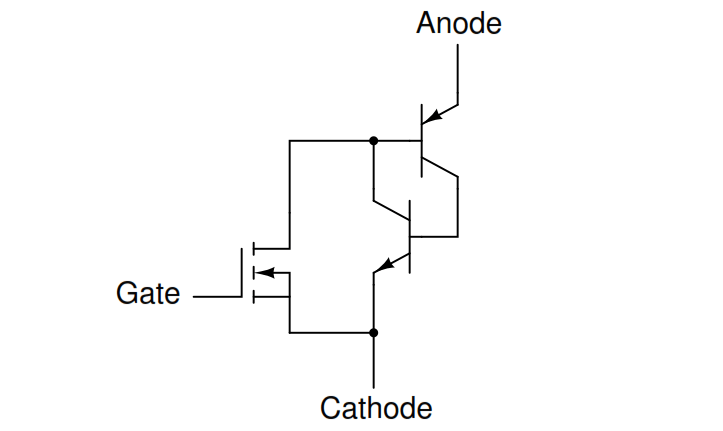
MOS-gated thyristor equivalent circuit
Given the fact that ordinary SCRs are quite easy to “drive” as it is, the practical advantage of using an even more sensitive device (a MOSFET) to initiate triggering is debatable.
Also, placing a MOSFET at the gate input of the thyristor now makes it impossible to turn it off by a reverse-triggering signal. Only low-current dropout can make this device stop conducting after it has been latched.
A device of arguably greater value would be a fully-controllable thyristor, whereby a small gate signal could both trigger the thyristor and force it to turn off. Such a device does exist, and it is called the MOS Controlled Thyristor, or MCT.
It uses a pair of MOSFETs connected to a common gate terminal, one to trigger the thyristor and the other to “un-trigger” it: (Figure below)
MOS-controlled thyristor (MCT) equivalent circuit
A positive gate voltage (with respect to the cathode) turns on the upper (N-channel) MOSFET, allowing base current through the upper (PNP) transistor, which latches the transistor pair in an “on” state.
Once both transistors are fully latched, there will be little voltage dropped between anode and cathode, and the thyristor will remain latched as long as the controlled current exceeds the minimum (holding) current value.
However, if a negative gate voltage is applied (with respect to the anode, which is at nearly the same voltage as the cathode in the latched state), the lower MOSFET will turn on and “short” between the lower (NPN) transistor’s base and emitter terminals, thus forcing it into cut-off.
Once the NPN transistor cuts off, the PNP transistor will drop out of conduction, and the whole thyristor turns off. Gate voltage has full control over conduction through the MCT: to turn it on and to turn it off.
This device is still a thyristor, though. If zero voltage is applied between gate and cathode, neither MOSFET will turn on. Consequently, the bipolar transistor pair will remain in whatever state it was last in (hysteresis).
So, a brief positive pulse to the gate turns the MCT on, a brief negative pulse forces it off, and no applied gate voltage lets it remain in whatever state it is already in. In essence, the MCT is a latching version of the IGBT (Insulated Gate Bipolar Transistor).
A MOS-gated thyristor uses an N-channel MOSFET to trigger a thyristor, resulting in an extremely low gate current requirement.
A MOS Controlled Thyristor, or MCT, uses two MOSFETS to exert full control over the thyristor. A positive gate voltage triggers the device; a negative gate voltage forces it to turn off. Zero gate voltage allows the thyristor to remain in whatever state it was previously in (off, or latched on).
Initially, AC motors were constructed like DC motors. Numerous problems were encountered due to changing…
Learn about the AC Instrumentation Transducers like Potentiometer, LVDT, RVDT, Synchro, and Capacitive Transducers.
AC bridge circuit unknown impedance is balanced by a standard impedance of similar type on…
Power Quality is the general term given to represent an AC power system freedom from harmonic…
Hall effect - Voltage is proportional to current and strength of the perpendicular magnetic field.…
Learn about the Frequency and Phase Measurement from our free online electronics and electrical engineering…

