There are circumstances when you may need to analyze a DC reactive circuit when the starting values of voltage and current are not respective of a fully ”discharged” state.
In other words, the capacitor might start at a partially-charged condition instead of starting at zero volts, and an inductor might start with some amount of current already through it, instead of zero as we have been assuming so far.
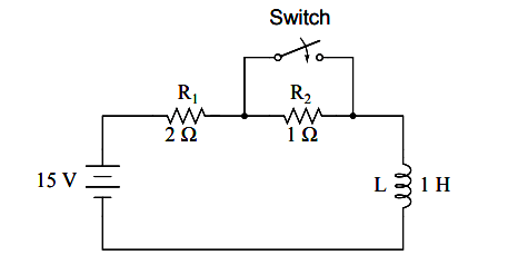
Take this circuit as an example, starting with the switch open and finishing with the switch in the closed position:
Since this is an inductive circuit, we’ll start our analysis by determining the start and end values for current.
This step is vitally important when analyzing inductive circuits, as the starting and ending voltage can only be known after the current has been determined! With the switch open (starting condition), there is a total (series) resistance of 3 Ω, which limits the final current in the circuit to 5 amps:
I = E/R
I = 15 V / 3 Ω
I = 5 A
So, before the switch is even closed, we have a current through the inductor of 5 amps, rather than starting from 0 amps as in the previous inductor example.
With the switch closed (the final condition), the 1 Ω resistor is shorted across (bypassed), which changes the circuit’s total resistance to 2 Ω. With the switch closed, the final value for current through the inductor would then be:
I = E/R
I = 15 V / 2 Ω
I = 7.5 A
So, the inductor in this circuit has a starting current of 5 amps and an ending current of 7.5 amps.
Since the ”timing” will take place during the time that the switch is closed and R2 is shorted past, we need to calculate our time constant from L1 and R1: 1 Henry divided by 2 Ω, or τ = 1/2 second. With these values, we can calculate what will happen to the current over time.
The voltage across the inductor will be calculated by multiplying the current by 2 (to arrive at the voltage across the 2 Ω resistor), then subtracting that from 15 volts to see what’s left.
If you realize that the voltage across the inductor starts at 5 volts (when the switch is first closed) and decays to 0 volts over time, you can also use these figures for starting/ending values in the general formula and derive the same results:
Initially, AC motors were constructed like DC motors. Numerous problems were encountered due to changing…
Learn about the AC Instrumentation Transducers like Potentiometer, LVDT, RVDT, Synchro, and Capacitive Transducers.
AC bridge circuit unknown impedance is balanced by a standard impedance of similar type on…
Power Quality is the general term given to represent an AC power system freedom from harmonic…
Hall effect - Voltage is proportional to current and strength of the perpendicular magnetic field.…
Learn about the Frequency and Phase Measurement from our free online electronics and electrical engineering…

