Inst ToolsInst ToolsInst Tools
  • Courses
  • Automation
    • PLC
    • Control System
    • Safety System
    • Communication
    • Fire & Gas System
  • Instrumentation
    • Design
    • Pressure
    • Temperature
    • Flow
    • Level
    • Vibration
    • Analyzer
    • Control Valve
    • Switch
    • Calibration
    • Erection & Commissioning
  • Interview
    • Instrumentation
    • Electrical
    • Electronics
    • Practical
  • Q&A
    • Instrumentation
    • Control System
    • Electrical
    • Electronics
    • Analog Electronics
    • Digital Electronics
    • Power Electronics
    • Microprocessor
  • Request
Search
  • Books
  • Software
  • Projects
  • Process
  • Tools
  • Basics
  • Formula
  • Power Plant
  • Root Cause Analysis
  • Electrical Basics
  • Animation
  • Standards
  • 4-20 mA Course
  • Siemens PLC Course
Reading: Short Notes on Different Valve Types
Share
Font ResizerAa
Inst ToolsInst Tools
Font ResizerAa
  • Courses
  • Design
  • PLC
  • Interview
  • Control System
Search
  • Courses
  • Automation
    • PLC
    • Control System
    • Safety System
    • Communication
    • Fire & Gas System
  • Instrumentation
    • Design
    • Pressure
    • Temperature
    • Flow
    • Level
    • Vibration
    • Analyzer
    • Control Valve
    • Switch
    • Calibration
    • Erection & Commissioning
  • Interview
    • Instrumentation
    • Electrical
    • Electronics
    • Practical
  • Q&A
    • Instrumentation
    • Control System
    • Electrical
    • Electronics
    • Analog Electronics
    • Digital Electronics
    • Power Electronics
    • Microprocessor
  • Request
Follow US
All rights reserved. Reproduction in whole or in part without written permission is prohibited.
Inst Tools > Blog > Control Valves > Short Notes on Different Valve Types

Short Notes on Different Valve Types

Last updated: May 16, 2019 9:38 am
Editorial Staff
Control Valves
5 Comments
Share
6 Min Read
SHARE

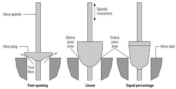
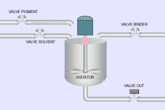
The essential function of a valve is to start, throttle and stop a fluid flow. Throttling, as shown in Below Figure, means regulating or controlling the rate of fluid flow.

Contents
Different Valve Types1. Globe valves2. Gate valves3. Needle valves4. Pinch valves5. Diaphragm valves6. Plug valves7. Ball valves8. Butterfly valves

Different Valve Types

Control Valve Functions

1. Globe valves

Globe valves are the most widely used in industry for flow control in both on/off and throttling service. They typically have rounded bodies from which their name is derived.

They are linear motion valves with a tapered plug or disk attached to the stem that closes onto a seating surface to act as flow control element, as shown in Below Figure.

The liquid must make two 90° turns when passing through the valve and because of that, the pressure drop in the globe valve is significant, even when fully open. The high pressure drop is the main disadvantage of the globe valve.

Globe Valve Principle

2. Gate valves

Gate valves (also known as knife valves or slide valves) are the most common valve used for on/off service but could be used for throttling. They are linear motion valves and a flat disk or wedge slides into the flow stream to act as flow control element, as shown in Below Figure.

The direction of fluid flow is not changed by the valve. When fully open, the wedge completely clears the flow path creating minimum pressure drop.

Gate valves are advantageous in applications involving slurries, as their ‘gates’ can cut right through the slurry. They are also used in applications that involve viscous liquids such as heavy oils, light grease, varnish, molasses, honey and cream.

Gate Valve Principle

3. Needle valves

A needle valve, shown in Below Figure, is used to make relatively fine adjustments to the fluid flow and can be used for on/off and throttling service.

They are linear motion valves with a tapered ‘needle like’ cone shaped plug that acts as the flow control element. The fluid enters from below into the seat which forms part of the flow path.

The needle plug permits the flow opening in this channel to be increased or decreased very gradually. Needle valves are widely used for steam, air, gas, water or other non-viscous liquids.

Disadvantages of the needle valve are a large pressure loss and possible clogging of the flow orifice.

Needle Valve Principle

4. Pinch valves

The relatively inexpensive pinch valve, illustrated In Below Figure, is the simplest of all the valve designs and may be used for on/off and throttling service.

Pinch valves are linear motion valves that use a flexible tube or sleeve to effect valve closure.

Pinch valves are ideally suited for the handling of slurries, liquids with large amounts of suspended solids and corrosive chemicals.

Pinch Valve Principle

5. Diaphragm valves

A diaphragm valve, illustrated in Below Figure, is related to pinch valves and one of the oldest types of valve known. Leather diaphragm valves were used by Greeks and Romans to control the temperature of their hot baths.

Diaphragm valves use linear stem movement for on/off and throttling and are excellent for controlling fluid flow containing suspended solids.

A stud moves a flexible and resilient diaphragm into the flow thereby acting as flow control element. The diaphragm valve is used primarily for handling viscous and corrosive fluids as well as slurries.

Diaphragm valve Principle

6. Plug valves

Plug valves, illustrated in Below Figure, are also called plug cock or stop cock valves and they also date back to ancient times, when used by Romans in plumbing systems.

Today they remain one of the most widely used valves for both on/off and throttling services. A plug valve is a rotary moving valve that uses a cylindrical or tapered plug as the flow control element.

The opening through the plug may be rectangular or round. Flow is regulated from closed to open during a 90° turn. If the opening is the same size or larger than the pipe’s inside diameter, it is referred to as a full port otherwise as standard round port.

Full port plug valves offer little resistance to flow when fully open, resulting in small pressure loss. A disadvantage off plug valves is its poor throttling characteristics.

Plug valve Principle

7. Ball valves

Ball valves, illustrated in Below Figure, are related to plug valves and are used in situations where tight shut-off is required. Ball valves are rotational motion valves and are used for on/off and throttling service. The flow control element is a sphere with a round opening rotating in a spherical seat.

Flow is regulated from closed to open during a 90° turn. Full port ball valves create a minimum pressure loss when fully open. A disadvantage of the ball valve is its poor throttling characteristics.

Ball valve Principle

8. Butterfly valves

A butterfly valve, illustrated in Below Figure, is a rotary movement valve used for on/off flow control and especially in throttling applications. The flow control element in butterfly valves is a circular disk with its pivot axis at right angles to the direction of flow.

A 90° turn of the axis moves the valve from closed to open. Butterfly valves are well suited to handle large flows of liquids or gasses as well as slurries and liquids with large amounts of suspended solids.

Butterfly valve Principle

Don't Miss Our Updates
Be the first to get exclusive content straight to your email.
We promise not to spam you. You can unsubscribe at any time.
Invalid email address
You've successfully subscribed !

Continue Reading

Basic Parts of Control Valves
Valve Basics, Sizing, and Actuators Books
What happens when Fluid Flow Reversed through Control Valve?
Digital Control Valves – Introduction, Principle, Setup, Applications
Control Valve Passing Problem after Overhauling Job
Pressure Relief Valve Principle
Share This Article
Facebook Whatsapp Whatsapp LinkedIn Copy Link
Share
5 Comments
  • Mohan Naik says:
    November 2, 2016 at 4:20 pm

    Useful Information

    Reply
  • Bhargav Reddy says:
    August 31, 2017 at 4:04 am

    Sir
    Can You give information about steam turbine HP valve and LP valve(Extraction) and ESV valve. Woodward’s governor 505E types and details.

    Reply
    • S Bharadwaj Reddy says:
      August 31, 2017 at 5:51 am

      Hi, Requested Topic Noted. It takes some time but you will get some info. Thanks

      Reply
  • G Kameswara Rao says:
    July 25, 2018 at 8:02 pm

    Thank you so much. Excellent info.

    Reply
  • Abdulgader Banun says:
    April 23, 2022 at 2:14 pm

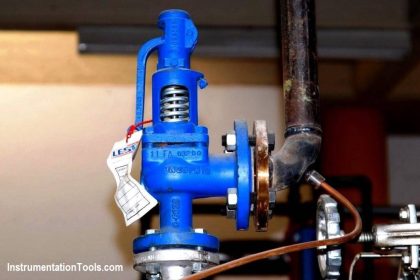
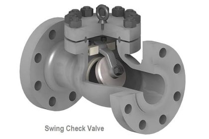
    Would, please, give more details of Valves used in Oil & Gas fields

    Reply

Leave a Reply Cancel reply

Your email address will not be published. Required fields are marked *

Stay Connected

128.3kFollowersLike
69.1kFollowersFollow
210kSubscribersSubscribe
38kFollowersFollow

Categories

Explore More

Hunting of Control Valves
Rotork Motor Operated Valve Basic Configuration
Control Valves Multiple Choice Questions
How to Reduce the Control Valve Noise?
Control Valve Cv calculation
Interview Questions on Control Valves
Air Filter Regulator Working Principle Animation
PID Controller Action : Directing Acting & Reverse Acting

Keep Learning

Electric Motor Actuators

What is Motor Actuator ?

Volume Booster Working Principle

Control Valve Volume Booster Working Principle

3-way solenoid valve Normally Open

What is a 3-way Solenoid Valve ?

Identify Valve Parts Quiz with Answers

Identify Valve Parts Quiz with Answers

Online Testing of Solenoid Valve

Design and Accessories Required for Online Testing of Solenoid Valve

What is Pump Cavitation

What is Pump Cavitation? How to Avoid Cavitation?

Single Port Globe Valve

How Sliding Stem Valves Work ?

CONTROL VALVE CHARACTERISTICS

Difference between Quick Opening, Linear & Equal Percentage Control Valve characteristics

Learn More

Compressor IP Case Discharge Temperature Gradually Increases

Compressor Anti-Surge Control near-miss incident

Burning Oven PLC Program

PLC Program for Ceramic Burning Oven Conveyor System

What is a Spare Part

What is a Spare Part? Classification, Cost, Critical Inventory

HT motors Corrosion Problem

HT motors Corrosion Problem

Single Phase Half-controlled Rectifier RL Load With FD

Phase-Controlled Half-Wave Rectifier With Freewheeling Diode

HART Communication Problems

HART Communication Problems

Instrumentation Engineering Materials Test

Instrumentation Materials Test

Pinch Valve

What is Pinch Valve ?

Menu

  • About
  • Privacy Policy
  • Copyright

Quick Links

  • Learn PLC
  • Helping Hand
  • Part Time Job

YouTube Subscribe

Follow US
All rights reserved. Reproduction in whole or in part without written permission is prohibited.
Welcome Back!

Sign in to your account

Username or Email Address
Password

Lost your password?