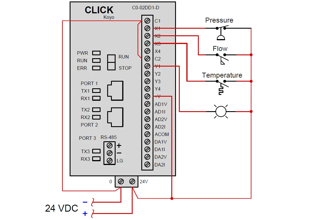
Suppose we have a PLC connected to three process switches as shown in this illustration:
In the above diagram :
Determine the switch actuation statuses (i.e. low versus high process stimulus) given the “live” display of the ladder logic program shown here:
Also, determine the status of the lamp connected to the PLC’s Y1 output.
Share Your Answer / Comments
Credits : Tony R. Kuphaldt – under CC BY 1.0
This PLC example on manufacturing line assembly is an intermediate-level PLC program prepared for the…
In this article, you will learn the PLC programming example with pushbutton and motor control…
This article teaches how to convert Boolean logic to PLC programming ladder logic with the…
In this article, you will learn the PLC programming example on timers function block using…
Design a program for PLC pump control such that the pump must be turned ON…
Polyvinyl alcohol (PVA) is a water-soluble and biodegradable synthetic polymer used in oil field cementing…


View Comments
The lamp will be energized when pressure & flow high & temp low