In order to accurately calibrate a pressure instrument in a shop environment, we must create fluid pressures of known magnitude against which we compare the instrument being calibrated.
As with other types of physical calibrations, our choice of standards falls into two broad categories: devices that inherently produce known pressures versus devices that accurately measure pressures created by some (other) adjustable source.
A deadweight tester (sometimes referred to as a dead-test calibrator) is an example in the former category. These devices create accurately known pressures by means of precise masses and pistons of precise area:
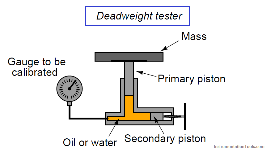
After connecting the gauge (or other pressure instrument) to be calibrated, the technician adjusts the secondary piston to cause the primary piston to lift off its resting position and be suspended by oil pressure alone.
So long as the mass placed on the primary piston is precisely known, Earth’s gravitational field is constant, and the piston is perfectly vertical, the fluid pressure applied to the instrument under test must be equal to the value described by the following equation:

Where,
P = Fluid pressure
F = Force exerted by the action of gravity on the mass (Fweight = mg)
A = Area of piston
The primary piston area, of course, is precisely set at the time of the deadweight tester’s manufacture and does not change appreciably throughout the life of the device.
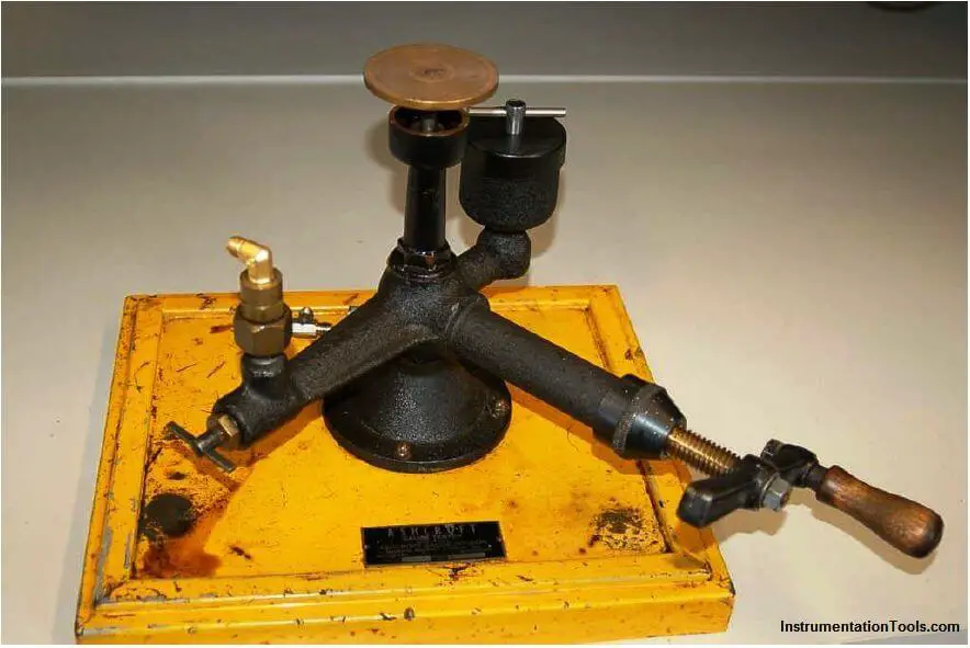
A very simple deadweight tester unit appears in the next photograph, mounted to a yellow wooden base:
When sufficient pressure has been accumulated inside the tester to overcome the weight on the piston, the piston rises off its rest and “floats” on the pressurized oil, as shown in this close-up photograph:
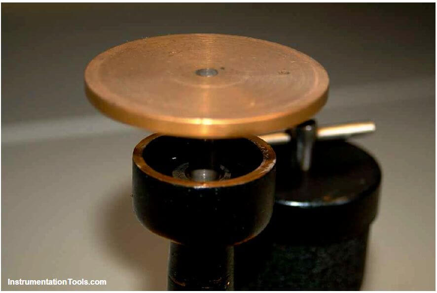
A common operating practice for any deadweight tester is to gently spin the mass during testing so the primary piston continually rotates within its cylinder.
Any motion will prevent static friction from taking hold, helping to ensure the only force on the primary piston is the force of the fluid within the deadweight tester.
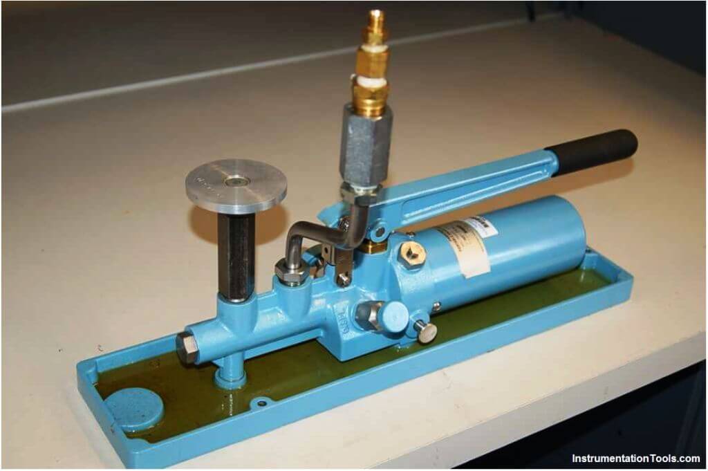
Most modern deadweight testers include extra features such as hand pumps and bleed valves in addition to secondary pistons, to facilitate both rapid and precise operation.
The next photograph shows a newer deadweight tester, with these extra features:
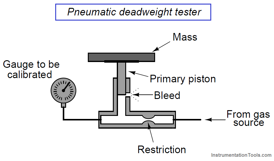
There is also such a thing as a pneumatic deadweight tester. In these devices, a constant flow of gas such as compressed air or bottled nitrogen vents through a bleed port operated by the primary piston.
The piston moves as necessary to maintain just enough gas pressure inside the unit to suspend the mass(es) against gravity. This gas pressure passes on to the instrument under test, just as liquid pressure in a hydraulic deadweight tester passes to the test instrument for comparison:
In fact, the construction and operation of a pneumatic deadweight tester is quite similar to a self-balancing (force-balance) pneumatic instrument mechanism with a baffle/nozzle assembly.
A moving element opens or closes a variable restriction downstream of a fixed restriction to generate a varying pressure. In this case, that pressure directly operates the bleed vent to self-regulate gas pressure at whatever value is necessary to suspend the mass against gravity.
Deadweight testers (both hydraulic and pneumatic) lend themselves well to relatively high pressures, owing to the practical limitations of mass and piston area.
You could use a deadweight tester to calibrate a 100 PSI pressure gauge used for measuring water mains pressure, for example, but you could not use a deadweight tester to calibrate a 0 to 1 ”W.C. (zero to one inch water column) pressure gauge used to measure draft pressure in a furnace flue.
For low-pressure calibrations, the simple manometer is a much more practical standard. Manometers, of course, do not generate pressure on their own.
In order to use a manometer to calibrate a pressure instrument, you must connect both devices to a source of variable fluid pressure, typically instrument air through a precision pressure regulator:
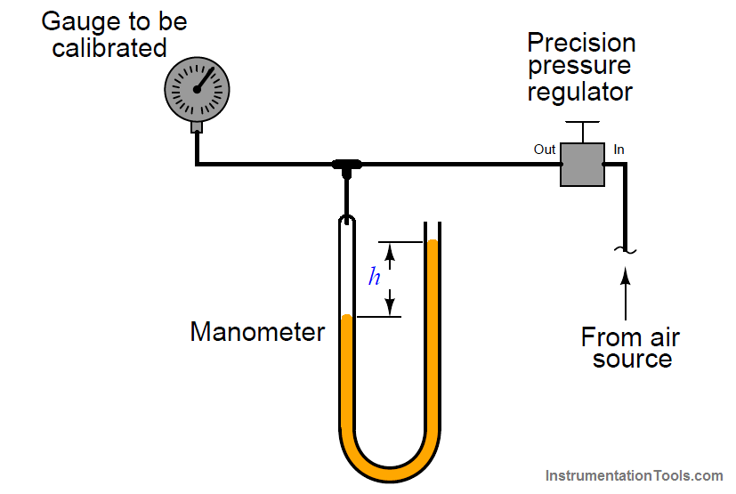
The difference in liquid column heights (h) within the manometer shows the pressure applied to the gauge.
As with the deadweight tester, the accuracy of this pressure measurement is bound by just a few physical constants, none of which are liable to sudden change.
So long as the manometer’s liquid density is precisely known, Earth’s gravitational field is constant, and the manometer tubes are perfectly vertical, the fluid pressure indicated by the manometer must be equal to the value described by the following equation (two different forms given):
P = ρgh (or) P = γh
Where,
P = Fluid pressure
ρ = Mass density of fluid
γ = Weight density of fluid
g = Acceleration of gravity
h = Height difference between manometer liquid columns
Of course, with pressure-measuring test instruments of suitable accuracy (preferably NIST traceable), the same sort of calibration jig may be used for virtually any desired range of pressures:
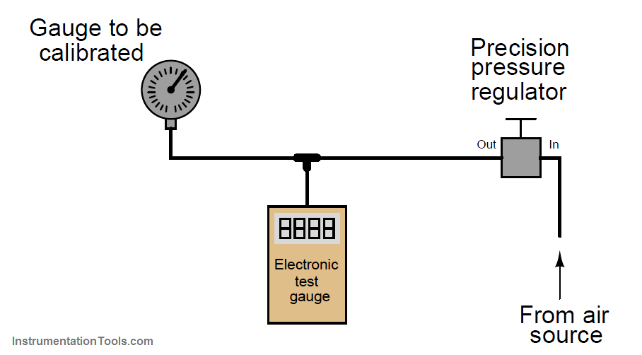
When the electronic test gauge is designed for very low pressures (inches of water column), they are sometimes referred to as electronic manometers.
Instrument calibrations performed in the field (i.e. in locations near or at the intended point of use rather than in a professionally-equipped shop) are almost always done this way: a pressure generating source is connected to both the instrument under test and a trusted calibration gauge (“test gauge”), and the two indications are compared at several points along the calibrated range.
Test equipment suitable for field pressure calibrations include slack-tube manometers made from flexible plastic tubing hung from any available anchor point near eye level, and test gauges typically of the helical bourdon tube variety.
Portable electronic test gauges are also available for field use, many with built-in hand pumps for generating precise air pressures.
A noteworthy example of a pneumatic pressure calibrator for field use was a device manufactured by the Wallace & Tiernan corporation, affectionately called a Wally box by at least one generation of instrument technicians.
A “Wally box” consisted of a large dial pressure gauge (several inches in diameter) with a multi-turn needle and a very fine scale, connected to a network of valves and regulators which were used to set different air pressures from any common compressed air source.
The entire mechanism was housed in an impact-resistance case for ruggedness. One of the many nice features of this calibration instrument was a selector valve allowing the technician to switch between two different pressures output by independent pressure regulators.
Once the two pressure regulator values were set to the instrument’s lower- and upper-range values (LRV and URV), it was possible to switch back and forth between those two pressures at will, making the task of adjusting an analog instrument with interactive zero and span adjustments much easier than it would have been to precisely adjust a single pressure regulator again and again.