Inst ToolsInst ToolsInst Tools
  • Courses
  • Automation
    • PLC
    • Control System
    • Safety System
    • Communication
    • Fire & Gas System
  • Instrumentation
    • Design
    • Pressure
    • Temperature
    • Flow
    • Level
    • Vibration
    • Analyzer
    • Control Valve
    • Switch
    • Calibration
    • Erection & Commissioning
  • Interview
    • Instrumentation
    • Electrical
    • Electronics
    • Practical
  • Q&A
    • Instrumentation
    • Control System
    • Electrical
    • Electronics
    • Analog Electronics
    • Digital Electronics
    • Power Electronics
    • Microprocessor
  • Request
Search
  • Books
  • Software
  • Projects
  • Process
  • Tools
  • Basics
  • Formula
  • Power Plant
  • Root Cause Analysis
  • Electrical Basics
  • Animation
  • Standards
  • 4-20 mA Course
  • Siemens PLC Course
Reading: Motor STAR – DELTA Starter Working Principle
Share
Font ResizerAa
Inst ToolsInst Tools
Font ResizerAa
  • Courses
  • Design
  • PLC
  • Interview
  • Control System
Search
  • Courses
  • Automation
    • PLC
    • Control System
    • Safety System
    • Communication
    • Fire & Gas System
  • Instrumentation
    • Design
    • Pressure
    • Temperature
    • Flow
    • Level
    • Vibration
    • Analyzer
    • Control Valve
    • Switch
    • Calibration
    • Erection & Commissioning
  • Interview
    • Instrumentation
    • Electrical
    • Electronics
    • Practical
  • Q&A
    • Instrumentation
    • Control System
    • Electrical
    • Electronics
    • Analog Electronics
    • Digital Electronics
    • Power Electronics
    • Microprocessor
  • Request
Follow US
All rights reserved. Reproduction in whole or in part without written permission is prohibited.
Inst Tools > Blog > Electrical Basics > Motor STAR – DELTA Starter Working Principle

Motor STAR – DELTA Starter Working Principle

Motor STAR – DELTA Starter Working principle. A Dual starter connects the motor terminals directly to the power supply. Hence, the motor is subjected to the full voltage of the power supply. Consequently, high starting current flows through the motor.

Last updated: November 1, 2023 3:39 pm
Editorial Staff
Electrical Basics
5 Comments
Share
5 Min Read
SHARE

A Dual starter connects the motor terminals directly to the power supply. Hence, the motor is subjected to the full voltage of the power supply.

Contents
Reduced Voltage StartersStar / Delta StartersHow does Motor Star-Delta Starter work?

Consequently, a high starting current flows through the motor. This type of starting is suitable for small motors below 5 hp (3.75 kW).

Reduced Voltage Starters

Reduced-voltage starters are employed with motors above 5 hp. Dual motor starters are available for motors less than 150 KW on 400 V and for motors less than 1 MW on 6.6 kV.

Supply reliability and reserve power generation dictate the use of reduced voltage or not to reduce the starting current of an induction motor, the voltage across the motor needs to be reduced.

This can be done by

  1. Autotransformer starter,
  2. Star-delta starter or
  3. Resistor starter.

Nowadays VVVF drive (VFD) used extensively for speed control serves this purpose also.

In a dual starter, the motor is directly fed from the line and in a star-delta starter then motor is started initially from the star and later during running from the delta. This is a starting method that reduces the starting current and starting torque.

The Motor must be delta-connected during a normal run, in order to be able to use this starting method.

The received starting current is about 30 % of the starting current during direct online start and the starting torque is reduced to about 25 % of the torque available at a D.O.L start.

Star / Delta Starters

Star/Delta starters are probably the most common reduced voltage starters in the 50Hz world. (Known as Wye/Delta starters in the 60Hz world). They are used in an attempt to reduce the start current applied to the motor during start as a means of reducing the disturbances and interference on the electrical supply.

Component: The Star/Delta starter is manufactured from three contactors, a timer, and a thermal overload. The contactors are smaller than the single contactor used in a Direct on Line starter as they control winding currents only.

The currents through the winding are 1√3 = 0.58 (58%) of the current in the line. this connection amounts to approximately 30% of the delta values. The starting current is reduced to one-third of the direct starting current.

How does Motor Star-Delta Starter work?

There are two contactors that are close during the run, often referred to as the main contactor and the delta contactor. These are AC3 rated at 58% of the current rating of the motor.

The third contactor is the star contactor only carries star current while the motor is connected in star. The current in star is one-third of the current in delta, so this contactor can be AC3 rated at one-third of the motor rating.

In operation, the Main Contactor (KM3) and the Star Contactor (KM1) are closed initially, and then after a period of time, the star contactor is opened, and then the delta contactor (KM2) is closed.

The control of the contactors is by the timer (K1T) built into the starter. The Star and Delta are electrically interlocked and preferably mechanically interlocked as well.

In effect, there are four states:

  1. OFF State: All Contactors are open
  2. Star State: The Main and the Star contactors are closed and the delta contactor is open. The motor is connected in star and will produce one-third of DOL torque at one-third of DOL current.
  3. Open State: The Main contactor is closed and the Delta and Star contactors are open. There is voltage on one end of the motor windings, but the other end is open so no current can flow. The motor has a spinning rotor and behaves like a generator.
  4. Delta State: The Main and the Delta contactors are closed. The Star contactor is open. The motor is connected to full line voltage and full power and torque are available.

This type of operation is called open transition switching because there is an open state between the star state and the delta state.
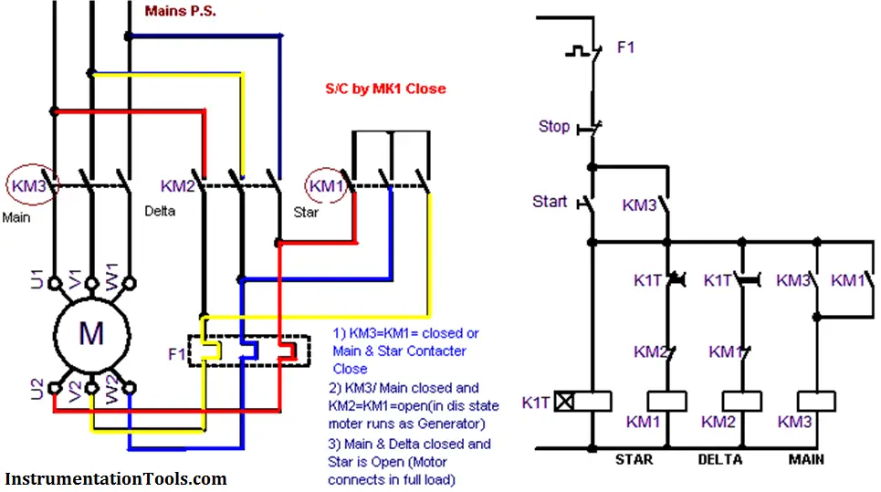
Motor STAR - DELTA Working principle

Also Read: Variable Frequency Drive Working Principle
Don't Miss Our Updates
Be the first to get exclusive content straight to your email.
We promise not to spam you. You can unsubscribe at any time.
Invalid email address
You've successfully subscribed !

Continue Reading

What is an ELV System? – Extra Low Voltage
What is a Relay? Types of Industrial Relays
Difference between Current Transformer and Potential Transformer
Electrical Engineering Documents – Engineers Questions
Assembling an Electrical Conduit Seal
Difference Between Permittivity and Permeability
Share This Article
Facebook Whatsapp Whatsapp LinkedIn Copy Link
Share
5 Comments
  • XYZ says:
    November 10, 2017 at 10:39 am

    Thanks for your wonderful site sir.It will be very useful.But,please provide the working principle of all the Equipments like Instruments,Electrical,Electronics,etc in automation.It will be more easy to understand practically.Expecting your work asap.

    Reply
  • sam says:
    March 4, 2021 at 2:47 pm

    good diagram but no explanatin on how the circuit is controllled

    Reply
  • Mohammed saeed dowelbite says:
    March 12, 2022 at 10:51 pm

    thank u for info & good explain circuits power and control

    Reply
  • Ammar says:
    March 13, 2022 at 6:44 pm

    Great article and good website.

    Kindly we need article explains control panel building and design and wiring

    Regards

    Reply
  • maseresha kumela says:
    December 8, 2023 at 8:48 pm

    IT is explanation of controlling cercute bast for all

    Reply

Leave a Reply Cancel reply

Your email address will not be published. Required fields are marked *

Stay Connected

128.3kFollowersLike
69.1kFollowersFollow
210kSubscribersSubscribe
38kFollowersFollow

Categories

Explore More

How does an Electric Motor Operate? – AC Motor Fundamentals
How does Electrical Power Outlet Work?
Types of Circuit Breakers, Advantages, Disadvantages
Motor Control Center – Purpose, Classification, and Advantages
Types of MCB
Design and Implement Motor Control – Electrical Engineering
Single Phase versus Three Phase Power
Geothermal Energy Power Plants

Keep Learning

Fence grounding specifications

All About Electric Fence Gates

Electrical Maintenance Engineer's Biggest Enemy

Electrical Components Overheating – Causes, Troubles, Prevent

UL 489 Circuit Breaker

Difference Between UL489 and UL1077

Introduction to Protective Systems

Introduction to Protective Systems

Lithium-ion Battery Charging System

Lithium-ion Battery Charging Systems

Time Delay Fuse

What is a Time Delay Fuse? – Principles and Advantages

ACSR (All Aluminium Conductor Steel Reinforced)

What is an Overhead Cable? Types of Overhead Conductors

Advantages of Three Phase System Compared to Single Phase System

Advantages of Three Phase System Compared to Single Phase System

Learn More

Chemical Reactor Vessel P and ID

Questions on Chemical Reactor Vessel P & ID

As-Interface Protocol Overview

AS-interface and DeviceNet Communication

Transmitter Performance and Calibration Frequency

How to Calculate Transmitter Performance and Calibration Frequency?

Power Systems Questions & Answers

Power Systems MCQ Series 19

process conditions, Find out the Circuit Components Status

As per Process Conditions, Find out the Circuit Components Status ?

Useful Trigonometry Website for Students Math Help

The Impact of Knowledge Management Platforms on Business Operations

DC Machine

DC Machines Construction

PLC Program using Logic GATEs

PLC Logic GATE Program

Menu

  • About
  • Privacy Policy
  • Copyright

Quick Links

  • Learn PLC
  • Helping Hand
  • Part Time Job

YouTube Subscribe

Follow US
All rights reserved. Reproduction in whole or in part without written permission is prohibited.
Welcome Back!

Sign in to your account

Username or Email Address
Password

Lost your password?