Efficiency is a very important specification of any type of electrical machine. When we talk about efficiency, losses comes into the picture. DC generator efficiency can be calculated by finding the total losses in it. There are various losses in DC generator. We classified DC generator losses into 3 types.
Losses in a D.C. Generator
(a) Copper Losses
(b) Magnetic Losses
(c) Mechanical Losses
The above 3 losses are primary losses in any type of electrical machine except in transformer. In transformer there are no rotating parts so no mechanical losses.
Let us have a brief discussion on each and every loss in dc generator.
(a) Copper Losses
Copper losses occur in dc generator when current passes through conductors of armature and field. Due the resistive property of conductors some amount of power wasted in the form of heat. Most of the time we neglect copper losses of dc generator filed, because the amount of current through the field is too low [Copper losses=I²R, I² will be negligible if I is too small].
Note : EgIa is the power output from armature.
If we consider all losses,
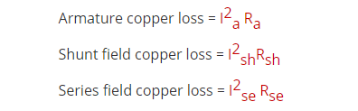
Total Copper Losses=I²Ra
Where Ra = resistance of armature and interpoles and series field winding etc.
This loss is about 30 to 40% of full-load losses.
(i) Field copper loss. In the case of shunt generators, it is practically constant and Ish² Rsh (or VIsh). In the case of series generator, it is = Ise²Rse where Rse is resistance of the series field winding. This loss is about 20 to 30% of F.L. losses.
(ii) The loss due to brush contact resistance. It is usually included in the armature copper loss.
Note: There’s additionally brush contact loss attributable to brush contact resistance (i.e., resistance in the middle of the surface of brush and commutator). This loss is mostly enclosed in armature copper loss.
(b) Magnetic Losses (also known as iron or core losses),
Hysteresis losses or Magnetic losses occur due to demagnetization of armature core. This losses are constant unless until frequency changes. Eddy current losses are due to circular currents in the armature core.
We know armature core is also a conductor, when magnetic flux cuts it, EMF will induce in the core, due to its closed path currents will flow. This currents causes eddy current losses.
(i) hysteresis loss, Wh ∝ B1.6 max f
(ii) eddy current loss, We ∝ B² max f ²
These losses are practically constant for shunt and compound-wound generators, because in their case, field current is approximately constant.
Both these losses total up to about 20 to 30% of F.L. losses.
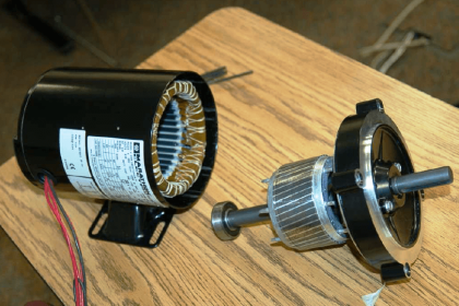
(c) Mechanical Losses
We know generator is a rotating machine it consist of friction loss at bearings and commutator and air-friction or windage loss of rotating armature. We can’t neglect this losses because they always present , These are about 10 to 20% of F.L. Losses.
The total losses in a d.c. generator are summarized below :
Stray Losses
Usually, magnetic and mechanical losses are collectively known as Stray Losses. These are also known as rotational losses for obvious reasons.
Total loss = armature copper loss + Wc = Ia²Ra + Wc = (I + Ish)²Ra + Wc.
Armature Cu loss Ia²Ra is known as variable loss because it varies with the load current.
Total loss = variable loss + constant losses Wc


I learned a lot through this application thank you