Inst ToolsInst ToolsInst Tools
  • Courses
  • Automation
    • PLC
    • Control System
    • Safety System
    • Communication
    • Fire & Gas System
  • Instrumentation
    • Design
    • Pressure
    • Temperature
    • Flow
    • Level
    • Vibration
    • Analyzer
    • Control Valve
    • Switch
    • Calibration
    • Erection & Commissioning
  • Interview
    • Instrumentation
    • Electrical
    • Electronics
    • Practical
  • Q&A
    • Instrumentation
    • Control System
    • Electrical
    • Electronics
    • Analog Electronics
    • Digital Electronics
    • Power Electronics
    • Microprocessor
  • Request
Search
  • Books
  • Software
  • Projects
  • Process
  • Tools
  • Basics
  • Formula
  • Power Plant
  • Root Cause Analysis
  • Electrical Basics
  • Animation
  • Standards
  • 4-20 mA Course
  • Siemens PLC Course
Reading: What is Kirchhoff’s Current Law
Share
Font ResizerAa
Inst ToolsInst Tools
Font ResizerAa
  • Courses
  • Design
  • PLC
  • Interview
  • Control System
Search
  • Courses
  • Automation
    • PLC
    • Control System
    • Safety System
    • Communication
    • Fire & Gas System
  • Instrumentation
    • Design
    • Pressure
    • Temperature
    • Flow
    • Level
    • Vibration
    • Analyzer
    • Control Valve
    • Switch
    • Calibration
    • Erection & Commissioning
  • Interview
    • Instrumentation
    • Electrical
    • Electronics
    • Practical
  • Q&A
    • Instrumentation
    • Control System
    • Electrical
    • Electronics
    • Analog Electronics
    • Digital Electronics
    • Power Electronics
    • Microprocessor
  • Request
Follow US
All rights reserved. Reproduction in whole or in part without written permission is prohibited.
Inst Tools > Blog > Electronic Devices & Circuits > What is Kirchhoff’s Current Law

What is Kirchhoff’s Current Law

Last updated: October 6, 2016 7:09 am
Editorial Staff
Electronic Devices & Circuits
No Comments
Share
4 Min Read
SHARE

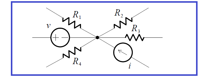
A connection of two or more elements is called a node. An example of a node is depicted in the partial circuit shown below:

Kirchhoff’s-Current-Law

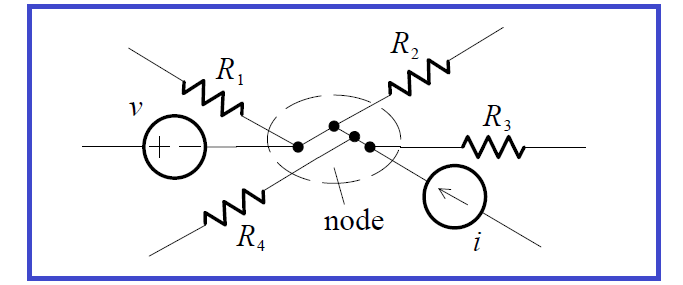
Even if the figure is redrawn to make it appear that there may be more than one node, as in the figure below, the connection of the six elements actually constitutes only one node.

Kirchhoff’s-Current-Law-Circuit

Kirchhoff’s  Current  Law  (KCL)  is  essentially  the  law  of  conservation  of electric charge. If currents directed out of a node are positive in sense, and currents directed into a node are negative in sense (or vice versa), then KCL can be stated as follows:

KCL defined

KCL: At any node of a circuit, the currents algebraically sum to zero.

If there are n elements attached to a node then, in symbols, KCL is:

KCL-Equation

KCL can also be stated as: The sum of the currents entering a node is equal to the sum of the currents leaving a node.

Now we will discuss about KCL law with practical examples below:

Example 1

As an example of KCL, consider a portion of some circuit, shown below:

example-of-KCL

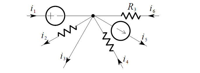
Choosing the positive sense to be leaving, we apply KCL at the node and obtain the equation:

– i1 + i2  + i3  – i4  + i5  – i6  = 0

Note that even if one of the elements – the one which carries i3– is a short circuit, KCL holds. In other words, KCL applies regardless of the nature of the elements in the circuit.

Example 2

We want to find the voltage v, in the two-node circuit shown below:

KCL-Example-the-two-node-circuit

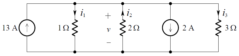
The directions of i1 , i2 , i3 and the polarity of v were chosen arbitrarily (the directions of the 13 A and 2 A sources are given). By KCL (at either of the two nodes), we have:

– 13 + i1 – i2  + 2 + i3  = 0

From this we can write:
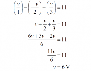
i1 – i2  + i3  = 11

By Ohm’s Law:

KCL-Formula-1

Substituting these into the previous equation yields:

KCL-Formula-2

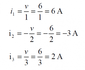
Having solved for v, we can now find that:

KCL-Formula-3

Just as KCL applies to any node of a circuit, so must KCL hold for any closed region, i.e. to satisfy the physical law of conservation of charge, the total current leaving (or entering) a region must be zero.

Example 3

In the circuit shown below, three regions have been identified:

kirchhoffs-current-law-example-circuit

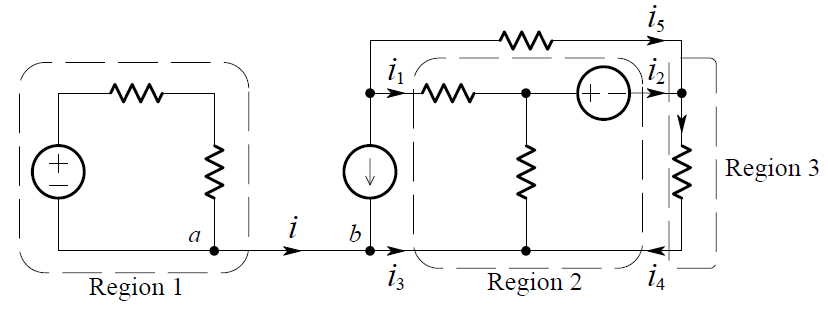
Applying KCL to Region 1, we get:

i = 0

For Region 2:

i1 + i3  + i4  = i2

For Region 3:

i2  + i5  = i4

You may now ask, “Since there is no current from point a to point b (or vice versa) why is the connection (a short-circuit) between the points there?” If the connection between the two points is removed, two separate circuits result. The voltages and currents within each individual circuit remain the same as before. Having the connection present constrains points a and b to be the same node, and  hence  be  at  the  same  voltage.  It  also  indicates  that  the  two  separate portions are physically connected (even though there is no current between them).

Don't Miss Our Updates
Be the first to get exclusive content straight to your email.
We promise not to spam you. You can unsubscribe at any time.
Invalid email address
You've successfully subscribed !

Continue Reading

Transistors Questions & Answers
Basic Electronics Questions & Answers
Capacitor Filter Working Principle
Circuit Elements and Types of Circuits
Power MOSFET Safe Operating Area
Electronic Symbols
Share This Article
Facebook Whatsapp Whatsapp LinkedIn Copy Link
Share
Leave a Comment

Leave a Reply Cancel reply

Your email address will not be published. Required fields are marked *

Stay Connected

128.3kFollowersLike
69.1kFollowersFollow
210kSubscribersSubscribe
38kFollowersFollow

Categories

Explore More

Bridge Rectifier Working Animation
Optocouplers Working Principle
Types of Resistors
Resistors Principle & Applications
Transistor Emitter Feedback Bias
Why Silicon is preferred over Germanium ?
Permanent Magnet Moving Coil Instruments (PMMC)
Basic Transistor Amplifier Circuit Principle

Keep Learning

photo-diode

Photodiode Working Principle

Full Wave Bridge Rectifier Operation

Full Wave Bridge Rectifier Operation

Types-of-diodes

Different Types of Diodes

diode-clamper-circuit

Full Wave Voltage Doubler using Diodes

Comparison of CB, CE & CC Amplifiers

Comparison of Transistor Configurations

Transistor Biasing

Transistor Biasing

Shockley Diode Working Principle

Shockley Diode Working Principle

Comparison of MOSFET and BJT

Comparison of MOSFET and BJT

Learn More

Load Cell Design

Load Cell Design

Siemens PLC Programming OBs in Siemens TIA Portal

FC Function in Siemens PLC

harmonics-effect-on-induction-motor

Harmonics effect on Induction Motor

PLC Program for Automatic Heating and Mixing of Products

Heating and Mixing of Products using PLC Example Tutorial

Importance of Unit Measurement

Importance of Unit Measurement

Difference Between Wattmeter and Energy Meter

Difference Between Wattmeter and Energy Meter

Digital Electronics Multiple Choice Questions

Read Only Memory (ROM) Objective Questions – Part 1

PLC Logic for Water Pumping and Chemical Addition

Developing PLC Logic for Water Pumping and Chemical Addition

Menu

  • About
  • Privacy Policy
  • Copyright

Quick Links

  • Learn PLC
  • Helping Hand
  • Part Time Job

YouTube Subscribe

Follow US
All rights reserved. Reproduction in whole or in part without written permission is prohibited.
Welcome Back!

Sign in to your account

Username or Email Address
Password

Lost your password?