Inst ToolsInst ToolsInst Tools
  • Courses
  • Automation
    • PLC
    • Control System
    • Safety System
    • Communication
    • Fire & Gas System
  • Instrumentation
    • Design
    • Pressure
    • Temperature
    • Flow
    • Level
    • Vibration
    • Analyzer
    • Control Valve
    • Switch
    • Calibration
    • Erection & Commissioning
  • Interview
    • Instrumentation
    • Electrical
    • Electronics
    • Practical
  • Q&A
    • Instrumentation
    • Control System
    • Electrical
    • Electronics
    • Analog Electronics
    • Digital Electronics
    • Power Electronics
    • Microprocessor
  • Request
Search
  • Books
  • Software
  • Projects
  • Process
  • Tools
  • Basics
  • Formula
  • Power Plant
  • Root Cause Analysis
  • Electrical Basics
  • Animation
  • Standards
  • 4-20 mA Course
  • Siemens PLC Course
Reading: Intrinsic Safety Protection ia and ib
Share
Font ResizerAa
Inst ToolsInst Tools
Font ResizerAa
  • Courses
  • Design
  • PLC
  • Interview
  • Control System
Search
  • Courses
  • Automation
    • PLC
    • Control System
    • Safety System
    • Communication
    • Fire & Gas System
  • Instrumentation
    • Design
    • Pressure
    • Temperature
    • Flow
    • Level
    • Vibration
    • Analyzer
    • Control Valve
    • Switch
    • Calibration
    • Erection & Commissioning
  • Interview
    • Instrumentation
    • Electrical
    • Electronics
    • Practical
  • Q&A
    • Instrumentation
    • Control System
    • Electrical
    • Electronics
    • Analog Electronics
    • Digital Electronics
    • Power Electronics
    • Microprocessor
  • Request
Follow US
All rights reserved. Reproduction in whole or in part without written permission is prohibited.
Inst Tools > Blog > Standards > Intrinsic Safety Protection ia and ib

Intrinsic Safety Protection ia and ib

Last updated: December 6, 2018 10:37 am
Editorial Staff
Standards
No Comments
Share
4 Min Read
SHARE

Difference Between ia and ib Intrinsic Safety Protection
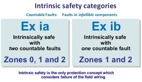
Intrinsic Safety Zones

ProtectionType ia

Apparatus is designed so that it is suitable for Zone 0 & it will not cause ignition when the maximum permitted values are applied to its terminals:

a) in normal operation with application of those non-countable faults which give the most onerous condition;

b) in normal operation with application of one countable fault and those non-countable faults which give the most onerous condition; and

c) in normal operation with application of two countable faults and those non-countable faults which give the most onerous condition.

Normal operation means that the apparatus conforms to the design specification supplied by the manufacturer, and is used within electrical, mechanical, and environmental limits specified by the manufacturer.

Normal operation also includes open circuiting, shorting, and grounding of external wiring at connection facilities. When assessing or testing for spark ignition, the safety factors to be applied to voltage or current are 1.5 in conditions a and b, and 1.0 in condition c. (These factors should properly be called “test factors.”

The real safety of intrinsic safety is inherent in the use of the sensitive IEC apparatus to attempt to ignite the most easily ignitable mixture of the test gas with hundreds of sparks. This combination of conditions is many times more onerous than any likely to occur in practice.)

North American Intrinsic Safety design standards are equivalent to ia intrinsic safety.

Intrinsic safety

ProtectionType ib

Apparatus is designed so that it is suitable for Zone 1, & it is assessed or tested under the conditions of a and b above, with a safety factor on voltage or current of 1.5 in the condition of a and b.

It is likely that Level of protection ic apparatus, equivalent to and replacing Type of Protection nL, suitable for use in Zone 2, will be standardized.

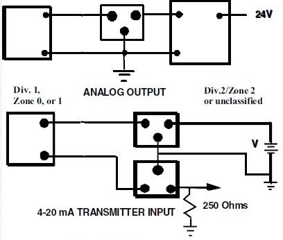
Figure typical grounded and ungrounded two wire intrinsically safe circuits.

Figure illustrates the principle that every ungrounded conductor entering the Division 1/Zone 0, or 1 location in this case where the transmitter or transducer is located, must be protected against unsafe voltage and current by appropriate associated apparatus. The boxes with three terminals represent barriers, independently certified protective assemblies, certified and rated according to the national standard. Nonintrinsically safe devices connected to the barrier need only be suitable for their location, and must not contain voltages higher than the Um rating of the barrier.

Many barriers are passive, consisting of current limiting resistors and voltage limiting diodes in appropriate configuration and redundancy to meet the requirements of the standard. Others have active current or voltage limiting. Both types may be combined with other circuitry for regulating voltages, processing signals, etc. The user should follow the recommendation of the intrinsically safe apparatus manufacturer in the control drawing, or discuss the selection of appropriate barriers with the barrier vendor, all of whom have proven configurations for many field mounted devices.

Also Read: ISA codes for Process Instrumentation

Don't Miss Our Updates
Be the first to get exclusive content straight to your email.
We promise not to spam you. You can unsubscribe at any time.
Invalid email address
You've successfully subscribed !

Continue Reading

Comparison of IEC & NEC Area Classifications
ISA codes for Process Instrumentation
Explosive Atmospheres & Hazardous Classification
Gas Detectors Standards
Instrumentation Standards
What are Technical Standards? – Importance, Types, Benefits
Share This Article
Facebook Whatsapp Whatsapp LinkedIn Copy Link
Share
Leave a Comment

Leave a Reply Cancel reply

Your email address will not be published. Required fields are marked *

Stay Connected

128.3kFollowersLike
69.1kFollowersFollow
210kSubscribersSubscribe
38kFollowersFollow

Categories

Explore More

Understanding Hazardous Area Classification
Flammable Facts
Difference Between IEC 60909 and IEC 61363 for Short Circuit
Zone vs Class / Division
Hazardous Area Classification markings
ATEX Ratings, Intrinsic Safety, Hazardous Areas and Explosive Atmospheres
NFPA Standards (National Fire Protection Association Standards)
Standard Temperature and Pressure Conditions

Keep Learning

NEMA to IP Ratings

NEMA Enclosure Types Standards

IEC 61508

What is IEC 61508 ?

IEC Area Classification System

Ex ic Intrinsic safety Standard

Instrumentation Standards

Electronic Equipment Purging Principles & Standards

Basics of Explosion Protection

Basics of Explosion Protection

Difference between Explosion Proof and Intrinsically Safe

Difference between Explosion Proof and Intrinsically Safe

NACE Standards - MR0103 Vs MR0175

NACE Standards – MR0103 Vs MR0175

Interview Questions & Answers on Alternators

Instrumentation Engineering Standards Questions & Answers

Learn More

Laminar Flow Meter Working Principle

Laminar Flow Meter Working Principle

SIL Levels

Understanding Safety Integrity Level IEC 61511

Pollution Monitoring Instruments Questions and Answers

Sulphur Di-oxide Monitoring Questions & Answers

Instrumentation Cyber Security Tips

How to Stop Cyber Attacks on PLC or DCS?

Design Process Control & Safety Systems

Design View of Supplying Process Control and Safety Systems

2-wire loop-powered transmitter

Loop Controller HART Signal Noise

Barometer Principle

What is a Barometer?

Single Line Diagram (SLD) Example

Electrical Drawings

Menu

  • About
  • Privacy Policy
  • Copyright

Quick Links

  • Learn PLC
  • Helping Hand
  • Part Time Job

YouTube Subscribe

Follow US
All rights reserved. Reproduction in whole or in part without written permission is prohibited.
Welcome Back!

Sign in to your account

Username or Email Address
Password

Lost your password?