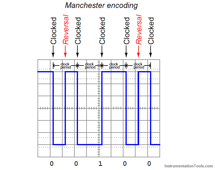
FOUNDATION Fieldbus H1 networks use Manchester encoding to represent bit states: a “high-to low” transition represents a logical zero (0), while a “low-to-high” transition represents a logical one (1). The following illustration shows how the data stream 00100 would be represented in Manchester encoding:

FF devices must be able to correctly distinguish between rising- and fall-edge signals in order to properly interpret the bit states of a Manchester-encoded signal. Any device interpreting these pulse edges “backwards” will invert every single bit! Thankfully, this problem is easy to avoid because the DC power supplied by the H1 segment wiring provides a “key” to identifying which wire is which, and therefore which pulses are rising-edge versus which pulses are falling-edge. For this reason, many (but not all!) FF devices are polarity-insensitive, automatically detecting the polarity of the network segment and compensating accordingly.
Every FF device draws at least 10 mA of current from the segment, and this current does not vary in the same manner that an analog (4-20 mA) device draws differing amounts of current under different operating conditions. Always remember that a Fieldbus device signals its variable(s) digitally, not by varying current. Old habits (and thought patterns) die hard, and so Fieldbus systems present challenges to technicians familiar with the behavior of analog current loop instrumentation. The amount of current drawn by any particular FF device depends on that device’s functionality – obviously, some will require more current for their operation than others. 10 mA to 30 mA should be considered a general range of current drawn by each FF device.
The standard operating voltage range for FF devices is between 9 and 32 volts DC. It is important to note, however, that not all manufacturers’ devices are in full compliance with the Fieldbus Foundation standard, and as such some may not operate properly at low voltages (near 9 volts DC)! The most common DC operating voltage for a FF network segment is 24 VDC (typical).
The minimum transmission voltage of a FF device is 750 millivolts peak-to-peak, while the minimum signal level for reception by a FF device is 150 millivolts peak-to-peak. This represents an acceptable attenuation of 5:1, or −14 dB between any two devices.
The PLC panel and MCC panel interface signals are start, stop, run feedback, trip, local…
In this article, we are going to discuss about shutter door control using induction motor…
Electrical Drives control the motion of electric motors. Motion control is required in industrial and…
PLC ladder logic design to control 3 motors with toggle switch and explain the program…
VFD simulator download: Master the online tool from the Yaskawa V1000 & programming software for…
The conveyor sorting machine is widely used in the packing industries using the PLC program…