Inst ToolsInst ToolsInst Tools
  • Courses
  • Automation
    • PLC
    • Control System
    • Safety System
    • Communication
    • Fire & Gas System
  • Instrumentation
    • Design
    • Pressure
    • Temperature
    • Flow
    • Level
    • Vibration
    • Analyzer
    • Control Valve
    • Switch
    • Calibration
    • Erection & Commissioning
  • Interview
    • Instrumentation
    • Electrical
    • Electronics
    • Practical
  • Q&A
    • Instrumentation
    • Control System
    • Electrical
    • Electronics
    • Analog Electronics
    • Digital Electronics
    • Power Electronics
    • Microprocessor
  • Request
Search
  • Books
  • Software
  • Projects
  • Process
  • Tools
  • Basics
  • Formula
  • Power Plant
  • Root Cause Analysis
  • Electrical Basics
  • Animation
  • Standards
  • 4-20 mA Course
  • Siemens PLC Course
Reading: Fiber Optic Cable Construction
Share
Font ResizerAa
Inst ToolsInst Tools
Font ResizerAa
  • Courses
  • Design
  • PLC
  • Interview
  • Control System
Search
  • Courses
  • Automation
    • PLC
    • Control System
    • Safety System
    • Communication
    • Fire & Gas System
  • Instrumentation
    • Design
    • Pressure
    • Temperature
    • Flow
    • Level
    • Vibration
    • Analyzer
    • Control Valve
    • Switch
    • Calibration
    • Erection & Commissioning
  • Interview
    • Instrumentation
    • Electrical
    • Electronics
    • Practical
  • Q&A
    • Instrumentation
    • Control System
    • Electrical
    • Electronics
    • Analog Electronics
    • Digital Electronics
    • Power Electronics
    • Microprocessor
  • Request
Follow US
All rights reserved. Reproduction in whole or in part without written permission is prohibited.
Inst Tools > Blog > Communication > Fiber Optic Cable Construction

Fiber Optic Cable Construction

Last updated: July 27, 2017 9:07 am
Editorial Staff
Communication
No Comments
Share
5 Min Read
SHARE

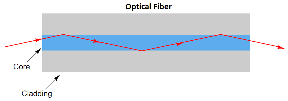
Communication-grade optical fibers are manufactured from fused silica (SiO2) glass of exceptional purity. A single strand of optical fiber made from this glass called the “core” serves as a waveguide for the light. The core is surrounded by another layer of glass called the “cladding” which has a different index of refraction necessary to “channel” the majority of the optical energy through the core and inhibit “leakage” of optical power from the cable. Additional layers of plastic and other materials around the core/cladding center provide coloring (for fiber identification in multi-fiber cables), protection against abrasion, and tensile strength so the cable will not suffer damage when pulled through conduit.

The purpose of building a fiber optic cable with a core and a cladding having different refractive indices (i.e. different speeds of light) is to exploit a phenomenon called total internal reflection, whereby rays of light reflect off the interface between core and cladding to prevent its unintentional escape from the core at any point along the length of the fiber.

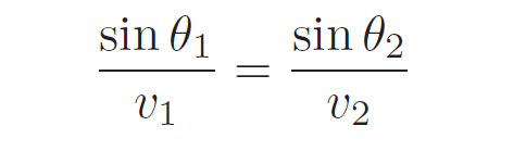
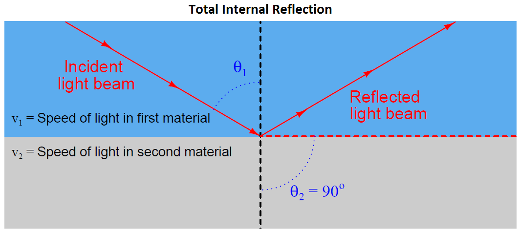
When light crosses an interface between two materials having different speeds, the light beam will become refracted as a function of those two speeds as described by Snell’s Law:

Fiber Optic Cable Construction

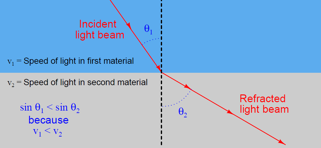
Snell’s Law relates the sine of the incident angle to the sine of the refracted angle as a ratio to each material’s speed of light, the material possessing the greatest speed of light (i.e. the lowest refractive index value) exhibiting the greatest angle as measured from perpendicular to the interface:

Snell’s Law

According to Snell’s Law, there will be a critical angle at which the incident light ray will refract to being parallel to the interface. Beyond this critical angle, the light ray ideally reflects off the interface and never enters the second material at all. This is the condition of total internal reflection, and it is what we desire in an optical fiber where the core is the first material and the cladding is the second material:

Fiber Optic Cable Construction-1

Optical Fiber

Both the core and cladding of an optical fiber are manufactured from the same base material of ultra-pure fused silica, but “doped” with specific impurities designed to alter the refractive index of each one (raising the refractive index of the core to decrease its optical velocity and lowering the refractive index of the cladding to increase its optical velocity). The diameter of core and cladding vary with the type of optical fiber, but several standard sizes have emerged in the industry, each one specified by the diameter of the core followed by the diameter of the cladding expressed in microns (millionths of a meter). A common optical fiber standard in the United States is 62.5/125 (62.5 micron core diameter, 125 micron cladding diameter), and 50/125 in Europe. Some less common standard core/cladding diameters include 85/125 and 100/140.

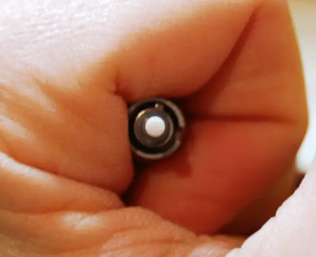
To give some perspective on the physical size of an optical fiber core, the following photograph shows the end-view of an “ST” style fiber optic connector for a 50/125 micron cable, held by my hand. A green LED light source is shining into the other end of this cable, the tiny green dot visible at the center of the ST connector revealing the diameter of the 50 micron core:

Optical Fiber Size

Several other layers of material must be placed over the core and cladding to form a rugged optical fiber. A plastic jacket with a typical diameter of 250 microns (0.25 mm) covers the cladding, and provides a base for color-coding the fiber. This three-layer construction of core, cladding, and jacket is known in the industry as Primary Coated Optical Fiber, or PCOF.

PCOF is still too fragile for end-user applications, and so another layer of plastic is typically added (900 microns in diameter) to make the fiber Secondary Coated Optical Fiber, or SCOF. When wrapped with fiberglass or Kevlar fibers around the secondary jacket for tensile strength, and a protective PVC plastic outer layer to protect against abrasion, the cable becomes suitable for indoor use. Cables suitable for outdoor, direct burial, and undersea applications usually take the form of groups of PCOF fibers packaged within an extremely rugged encasement with metal strands for tensile strength. Sometimes a gel material helps cushion the fibers from each other within the confines of the cable sheath.

Index & Credits

Don't Miss Our Updates
Be the first to get exclusive content straight to your email.
We promise not to spam you. You can unsubscribe at any time.
Invalid email address
You've successfully subscribed !

Continue Reading

Difference Between TCP and UDP
HART Protocol and Fieldbus Interview Questions
Interview Questions on Fieldbus Communication
Industrial Networking and Wireless Interview Questions
Overview of OPC Communication
Network Switch Requirement in SCADA and DCS Architecture
Share This Article
Facebook Whatsapp Whatsapp LinkedIn Copy Link
Share
Leave a Comment

Leave a Reply Cancel reply

Your email address will not be published. Required fields are marked *

Stay Connected

128.3kFollowersLike
69.1kFollowersFollow
210kSubscribersSubscribe
38kFollowersFollow

Categories

Explore More

Difference Between Modbus TCP IP and Profinet
Different Fieldbus Network Topologies
Difference Between Subnet and VLAN
HART Communication Tutorial Part 1
Difference between Fieldbus and Profibus
Latest ProfiBus Questions and Answers
Foundation Fieldbus (FF) Segment Topology
HART Communication Tutorial Part 4

Keep Learning

Ethernet Questions and Answers

Ethernet Communication Interview Questions & Answers

Networking Interview Questions

Top 100 Networking Interview Questions & Answers

7 OSI Layers of Communications

7 OSI Layers of Communication

Top 10 Facts about HART Technology

What is HART, Foundation Fieldbus & Profibus ?

Difference Between RS232 and RS485

Difference Between RS232 and RS485

Difference between Router, Switch, and Hub

Difference between Router, Switch, and Hub

Input function blocks

FF Function Blocks

HART Communication Tutorial 2

HART Communication Tutorial Part 5

Learn More

Analog Instruments

Explaining Various Types of Analog Instruments

Internal Parts of Globe Valve

How to Choose a Control Valve?

InTouch SCADA Password Protection

InTouch SCADA Login Password Security

Why is White Powder Used in Electrical Cables

Why is White Powder Used in Electrical Cables?

Accelerometer Vibration Probe

Accelerometer Vibration Probe Principle

DP type Flow Transmitter Preventive Maintenance

Troubleshooting DP type Transmitter Common Problems

Use Cryptographic checks for PLC

#5 PLC Best Practices – Cryptographic and Checksum Integrity Checks

Differential Pressure Transmitter with 5 Way Manifold Valve

Differential Pressure Transmitter with 5 Way Manifold Valve

Menu

  • About
  • Privacy Policy
  • Copyright

Quick Links

  • Learn PLC
  • Helping Hand
  • Part Time Job

YouTube Subscribe

Follow US
All rights reserved. Reproduction in whole or in part without written permission is prohibited.
Welcome Back!

Sign in to your account

Username or Email Address
Password

Lost your password?