Inst ToolsInst ToolsInst Tools
  • Courses
  • Automation
    • PLC
    • Control System
    • Safety System
    • Communication
    • Fire & Gas System
  • Instrumentation
    • Design
    • Pressure
    • Temperature
    • Flow
    • Level
    • Vibration
    • Analyzer
    • Control Valve
    • Switch
    • Calibration
    • Erection & Commissioning
  • Interview
    • Instrumentation
    • Electrical
    • Electronics
    • Practical
  • Q&A
    • Instrumentation
    • Control System
    • Electrical
    • Electronics
    • Analog Electronics
    • Digital Electronics
    • Power Electronics
    • Microprocessor
  • Request
Search
  • Books
  • Software
  • Projects
  • Process
  • Tools
  • Basics
  • Formula
  • Power Plant
  • Root Cause Analysis
  • Electrical Basics
  • Animation
  • Standards
  • 4-20 mA Course
  • Siemens PLC Course
Reading: Electrical Voltage and current Signals
Share
Font ResizerAa
Inst ToolsInst Tools
Font ResizerAa
  • Courses
  • Design
  • PLC
  • Interview
  • Control System
Search
  • Courses
  • Automation
    • PLC
    • Control System
    • Safety System
    • Communication
    • Fire & Gas System
  • Instrumentation
    • Design
    • Pressure
    • Temperature
    • Flow
    • Level
    • Vibration
    • Analyzer
    • Control Valve
    • Switch
    • Calibration
    • Erection & Commissioning
  • Interview
    • Instrumentation
    • Electrical
    • Electronics
    • Practical
  • Q&A
    • Instrumentation
    • Control System
    • Electrical
    • Electronics
    • Analog Electronics
    • Digital Electronics
    • Power Electronics
    • Microprocessor
  • Request
Follow US
All rights reserved. Reproduction in whole or in part without written permission is prohibited.
Inst Tools > Blog > Electrical Basics > Electrical Voltage and current Signals

Electrical Voltage and current Signals

Last updated: September 18, 2016 2:27 am
Editorial Staff
Electrical Basics
No Comments
Share
5 Min Read
SHARE

Voltage and current levels in electrical engineering is very important. As any electrical system, equipment, devices all are characterized by their different voltage and current levels.

Voltage levels in Electrical system

Two types of voltage levels-

1. Nominal Voltage levels

  • Rated voltage designated for a system or equipment.
  • Rated voltage referring to some operating characteristics.

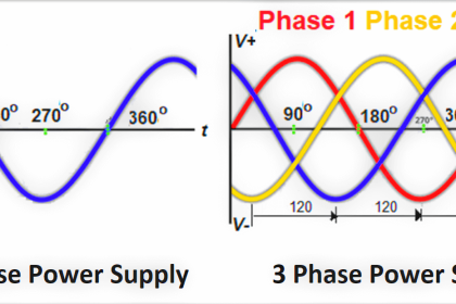
Say for a single phase motor the designated voltage is 220 volt as it is connected to a phase and a neutral; for a three phase motor which is
connected to three phases the designated voltage is 400V.
Now say for a protection system to be active, the energizing voltage has to be maintained within 10V to 20V DC- this is an operating characteristics. So 10V, 20V is also a nominal voltage levels.

2. Highest voltage level

  • Voltage by consideration of the insulation.
  • Highest voltage defined by the manufacturer or recommended by the manufacturer.

Electrical system insulation designed as per the voltage. So the highest voltage level will be the voltage which the system insulation can sustain.
Also the manufacturer defines some voltage restrictions for a certain electrical system or equipment. These all are highest voltage levels. Say an electrical system insulation highest voltage level is 11KV, but the connected electrical equipment highest voltage level is 5KV, as recommended by the manufacturer.

Some important concept to understand current levelsmcb

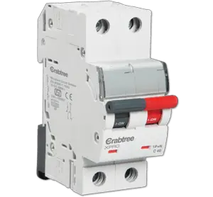
The definition of Circuit Breaker: A circuit breaker is an electrical device that is capable of break or make current in both the normal or abnormal (faulty) condition.

Make current: is closing the circuit breaker or establishing a connection. While closing the breaker there is high instantaneous non-linear current appears for short duration and the electrical system or equipment has to sustain this.

Break current is opening the circuit breaker or dis-engaging an electrical connection. This breaking current might be for normal operation or might be for abnormal/ faulty condition. While breaking current there is some time delay and the electrical system or equipment have to withstand high value of fault current during this short time.

If there is delay in breaking a connection while a fault occurred, the circuit breaker contacts might become welded by arc and large amount of heat.

Current levels in Electrical system

1. Rated current levels

– R.M.S value of a current that the electrical system or equipment can carry continuously. This is a normal operating current.

2. Rated short time withstand current

RMS value of a current that an electrical system or equipment can carry in closed position for a specified short duration such as 1s or 3s.

3. Rated peak withstand current

First major loop of the rated short time withstand current which an electrical system or equipment can carry in closed position.
For high voltage system rated peak withstand current is 2.5 times of rated short time withstand current.
For low voltage system rated peak with stand current is 1.5 to 2 times of rated short time withstand current.

4. Rated short circuit breaking current

rms value of maximum symmetrical short-circuit current in KA, which a circuit breaker shall be capable of breaking.
There are two values included in the rated short circuit breaking current-

  • RMS value of the ac component.
  • The percentage of DC component.

5.Rated short circuit making current

The maximum peak current the circuit breaker shall be able to close and latch again. This peak value is related to the RMS value of the rated short circuit breaking current, frequency and time constant.
As per ANSI/IEEE rated short circuit making current is also referred to as closing and latching capability.

Some specified value of rated short circuit breaking current are

If Rated short circuit making current=Ism and rated short circuit breaking current=Isb

  • Ism=2.5*Isb, At 50Hz and t=45 ms,
  • Ism=-2.6*Isb, at 60Hz, t=45ms.
  • Ism=-2.7*Isb, at both 50Hz and 60Hz, t=45ms.
Don't Miss Our Updates
Be the first to get exclusive content straight to your email.
We promise not to spam you. You can unsubscribe at any time.
Invalid email address
You've successfully subscribed !

Continue Reading

Difference Between MCB and MCCB
Difference between Power Cables and Signal Cables
How to Locate Faults in Cables? – Fault Analysis & Location
Totally Enclosed Fan Cooled (TEFC) Motors Rampant Winding Burnouts
Corona Discharge in Power Transmission Lines
Motor Control Timer Circuit – Automatic Motor START and STOP
Share This Article
Facebook Whatsapp Whatsapp LinkedIn Copy Link
Share
Leave a Comment

Leave a Reply Cancel reply

Your email address will not be published. Required fields are marked *

Stay Connected

128.3kFollowersLike
69.1kFollowersFollow
210kSubscribersSubscribe
38kFollowersFollow

Categories

Explore More

Pros and Cons of Soft Starter
Motor Protection Circuits
Difference Between Single Core and Multi-Core Cables
How Do Air Compressor Filters Clean and Protect the System?
What is an Intelligent Motor Control Center? – IMCC
Testing of Thermal Protection Relay for Motors
Difference between PVC, XLPE, and Insulated Cables
Single Phase versus Three Phase Power

Keep Learning

Phase Failure Relay

Why is Phase Failure Relay Required in LV Panels?

Difference Between Circuit Breaker and Disconnector

Difference Between Circuit Breaker and Disconnector

Induction Motor Operation

Induction Motor Over and Under Voltage Problems

Difference between Single-phase and three-phase power supply

Difference between Single-phase and Three-phase Power

Working of Stepper Motor

Types of Stepper Motors

Semiconductor Fuse

What is a Semiconductor Fuse?

Preventive Maintenance of Variable Frequency Drive

Preventive Maintenance of Variable Frequency Drive (VFD)

Types of Industrial Storage Batteries

Types of Industrial Storage Batteries

Learn More

Applications of CNC Machining

Important Applications of Rapid Prototype CNC Machining Services

Use Cryptographic checks for PLC

#5 PLC Best Practices – Cryptographic and Checksum Integrity Checks

Pressure Transmitters Filled impulse lines

Pressure Transmitters Filled impulse lines

Simatic Prosave HMI

How to Backup and Restore from Simatic Prosave HMI?

Node-RED in PLC Automation

Node-RED in PLC Industrial Automation

Control System Basic Wiring Practice Animation

PLC Connection between Instrument, Junction Box, Marshalling & System Cabinet

Swirl Flowmeters Principle

Swirl Flow Meters Working Principle

Ammonia Gas Detector Calibration

Ammonia Gas Detector Working Principle and Calibration

Menu

  • About
  • Privacy Policy
  • Copyright

Quick Links

  • Learn PLC
  • Helping Hand
  • Part Time Job

YouTube Subscribe

Follow US
All rights reserved. Reproduction in whole or in part without written permission is prohibited.
Welcome Back!

Sign in to your account

Username or Email Address
Password

Lost your password?