Inst ToolsInst ToolsInst Tools
  • Ask
  • Courses
  • Videos
  • Q & A
    • Interview
      • Instrumentation
      • Electronics
      • Electrical
      • Practical Questions
    • MCQ
      • Instrumentation MCQ
      • Electrical MCQ
      • Electronics MCQ
      • Control Systems MCQ
      • Analog Electronics MCQ
      • Digital Electronics MCQ
      • Power Electronics MCQ
      • Microprocessor MCQ
      • Multiple Choice Questions
  • EE
    • Electronics
      • Electronics Q & A
      • Electronic Basics
      • Electronic Devices & Circuits
      • Electronics Animation
      • Digital Electronics
    • Electrical
      • Electrical Basics
      • Electrical Q & A
      • Power Electronics
      • Electrical Machines
      • Electrical Animation
      • Power Systems
      • Switchgear & Protection
      • Transmission & Distribution
  • Measure
    • Control Valves
    • Calibration
    • Temperature
    • Pressure
    • Flow
    • Level
    • Analyzers
    • Switches
    • Vibration
    • Solenoid Valve
  • Control
    • PLC Tutorials
    • Control Systems
    • Safety Instrumented System (SIS)
    • Communication
    • Fire & Gas System
  • More
    • Design
    • Tools
    • Animation
    • Basics
    • Formulas
    • Standards
    • TextBooks
    • Common
    • Software
    • Excel Tools
    • Erection & Commissioning
    • Process Fundamentals
    • Videos
    • Books
Search
All rights reserved. Reproduction in whole or in part without written permission is prohibited.
Reading: Current Limiting Reactors in Power System
Share
Notification Show More
Font ResizerAa
Inst ToolsInst Tools
Font ResizerAa
  • Courses
  • PLC Tutorials
  • Control Systems
Search
  • Ask
  • Courses
  • Videos
  • Q & A
    • Interview
    • MCQ
  • EE
    • Electronics
    • Electrical
  • Measure
    • Control Valves
    • Calibration
    • Temperature
    • Pressure
    • Flow
    • Level
    • Analyzers
    • Switches
    • Vibration
    • Solenoid Valve
  • Control
    • PLC Tutorials
    • Control Systems
    • Safety Instrumented System (SIS)
    • Communication
    • Fire & Gas System
  • More
    • Design
    • Tools
    • Animation
    • Basics
    • Formulas
    • Standards
    • TextBooks
    • Common
    • Software
    • Excel Tools
    • Erection & Commissioning
    • Process Fundamentals
    • Videos
    • Books
Follow US
All rights reserved. Reproduction in whole or in part without written permission is prohibited.
Inst Tools > Blog > Transmission & Distribution > Current Limiting Reactors in Power System

Current Limiting Reactors in Power System

Last updated: September 19, 2016 2:32 am
Editorial Staff
Transmission & Distribution
No Comments
Share
5 Min Read
SHARE

Current Limiting Reactors are connected in series with the power system essentially to damp the short circuit fault current. During normal operation, a continuous current flows through the reactor. Current limiting reactors are now widely used to control fault currents in both utility and industrial power systems.

Current Limiting Reactors in Power System

The primary advantages of a current limiting reactor are:

  • Reduction of electromechanical loading and thermal stress of transformers and switchgears.
  • Improvement of the stability of primary bus voltage during a fault on feeder
  • Reduction of Line to line fault current to levels below those of line to ground faults or vice versa.
  • Protection of distribution transformer and downstream power equipment and devices from the propagation of initial fast front voltage transients due to faults and circuit breaker operations.
  • Increase in system reliability.

This type of reactors are briefly classified as :

PHASE REACTORS :

PHASE REACTORS

This type of reactor is connected in series with the transmission or distribution lines and is used to reduce fault level at the output of the reactor to the desirable level. They carry a continuous current during normal operation and hence Power loss is an important consideration. A dry type air core reactor by design has a high Q factor and hence preferred for this application. A low loss reactor can bring substantial benefit to the customer during course of life of the equipment.BUS TIE REACTORS :

 BUS TIE REACTORS

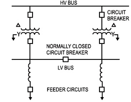
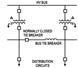
These reactors are used to tie two or more feeders or power sources are connected to a single bus. It is desirable to sectionalize the bus due to high fault levels without losing operational flexibility. The advantage of bus tie reactor is that if load is essentially balanced on both sides of the reactor under operating conditions, the reactor has negligible effect on voltage regulation or system losses. Quality Power can provide the customer a thorough solutions which includes :

The current limiting reactors are used to perform the following functions:

Functions of Reactors:

  • Protective reactors are used to reduce the flow of short circuit so as to protect  the apparatus from excessive mechanical stresses and from the overheating and thus protect the system as whole
  • Protective reactors are used to reduce the magnitude of the voltage disturbances caused by the short circuits
  • Reactors also localize the fault by limiting the current that flows into the fault from other healthy feeders or parts of the system, thereby avoiding the fault from spreading. This increases the chances of continuity of the supply
  • Reactors reduce the duty imposed on the switching equipment during the short circuits to be within economical ratings. So they are used (1) In the systems where extensions have been made and the circuit breaker rupturing capacities have become inadequate (2) In large systems, so as to limit the short circuit MVA to mach with the rupturing capacity of the circuit breakers

In general reactors should be placed at the points in the network where they can be most effective. Very few occasions arise where it is necessary or desirable to introduce reactance in the generator circuits as modern alternators have sufficient inherent reactance to enable them to withstand the forces of the short circuit. However when older machines operate in parallel with the older machines, a case may arise where the added reactance in the circuits of the older machines will provide protection and give them a roughly the same characteristics as the new machines

Reactors installed in the individual feeder circuits are not an economical proposition as often a considerable number of feeders are involved. Generally reactors are employed so that a group of feeders where the insertion of additional reactance is necessary to protect the group of circuit breakers of rupturing capacity. Similarly interconnection between the new and the old sections of the installation may profitably include a reactor and thus eliminate the need of replacing old circuit breakers

Don't Miss Our Updates
Be the first to get exclusive content straight to your email.
We promise not to spam you. You can unsubscribe at any time.
Invalid email address
You've successfully subscribed !
Conductor Size Selection in Distribution Power System
Advantages of Suspension Insulators and Pin type Insulators
Difference between Solid Conductor and Stranded Conductor
Charging Currents in Transmission Lines
Voltage Control Methods at Distribution System
Share This Article
Facebook Whatsapp Whatsapp LinkedIn Copy Link
Share
Leave a Comment

Leave a Reply Cancel reply

Your email address will not be published. Required fields are marked *

Stay Connected

128.3kFollowersLike
69.1kFollowersFollow
208kSubscribersSubscribe
38kFollowersFollow

Categories

Recent Comments

  • Kamli on Top Free PLC Software
  • Guifty Shimica on Top Non-PLC Certification Courses for Automation Professionals
  • Guifty Shimica on Top Non-PLC Certification Courses for Automation Professionals
  • MIHARITSOA Aina Sitraka on Top Non-PLC Certification Courses for Automation Professionals

Related Articles

Classification of Transmission Lines

Classification of Transmission Lines

Advantages of HVDC transmission

Advantages of HVDC transmission

Power Transmission And Distribution

Electrical Power Transmission And Distribution

advantages-disadvantages-of-ac-and-dc-power-transmission

Advantages & Disadvantages of AC and DC Power Transmission

Surge Impedance Loading of Transmission Line

Surge Impedance Loading of Transmission Line

Electrical Power Distribution

Electrical Power Distribution

Single Phase Earth Return System

Single Phase Earth Return System Advantages & Disadvantages

HVDC transmission compared to HVAC transmission

Comparison of HVDC transmission and HVAC transmission

More Articles

Wellhead Control Panel

Basics of Wellhead Control Panel (WHCP)

What is a Differential Mode Signal

Difference Between Differential Mode and Common Mode

Residual Current Circuit Breaker (RCCB)

Residual Current Circuit Breaker (RCCB)

Smart Transmitter Calibration Tutorial Part 2

Smart Transmitter Calibration Tutorial Part 2

diode-clamper-circuit

Full Wave Voltage Doubler using Diodes

Control Valve Passing Problem after Overhauling Job

Control Valve Passing Problem after Overhauling Job

Transistor Emitter Feedback Bias

Transistor Emitter Feedback Bias

Wonderware Recipe Manager Plus

What is Recipe Management in SCADA?

Follow US
All rights reserved. Reproduction in whole or in part without written permission is prohibited.
Welcome Back!

Sign in to your account

Username or Email Address
Password

Lost your password?