Thermocouples
What are Thermocouples?
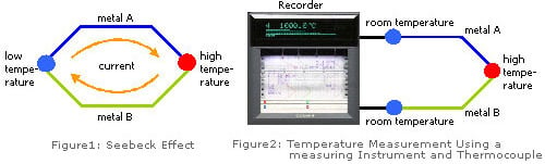
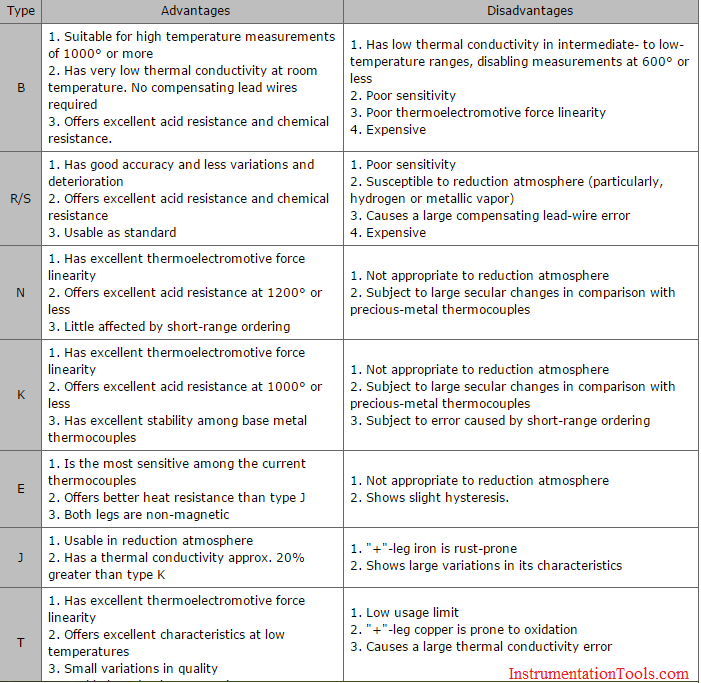
Thermocouples are temperature sensors. They operate under the principle that the junction of two dissimilar metals (forming a closed circuit) produces a measurable voltage (electromotive force) when the two ends of the thermocouple are at different temperatures (see Figure 1). Because thermocouples have simple construction and are superior in reliability, they have been used as industrial temperature sensors in a wide range of fields. Moreover, connecting a measuring instrument (recorders,DCS,PLC etc.) to one end of a circuit allows you to measure potential difference (electromagnetic force) (see Figure 2).
There are many types of thermocouples to measure diffrent range of temperature. Commonly-used types with superior characteristics have been standardized by JIS, IEC standards, and others. The following summarizes the typical thermocouple types (generally represented by symbols) and their features (advantages and disadvantages).
Thermocouples Advantages & Disadvantages
A thermocouple is comprised of at least two metals joined together to form two junctions. One is connected to the body whose temperature is to be measured; this is the hot or measuring junction. The other junction is connected to a body of known temperature; this is the cold or reference junction. Therefore the thermocouple measures unknown temperature of the body with reference to the known temperature of the other body.
-
Working Principle
The working principle of thermocouple is based on three effects, discovered by Seebeck, Peltier and Thomson. They are as follows:
1) Seebeck effect: The Seebeck effect states that when two different or unlike metals are joined together at two junctions, an electromotive force (emf) is generated at the two junctions. The amount of emf generated is different for different combinations of the metals.
2) Peltier effect: As per the Peltier effect, when two dissimilar metals are joined together to form two junctions, emf is generated within the circuit due to the different temperatures of the two junctions of the circuit.
3) Thomson effect: As per the Thomson effect, when two unlike metals are joined together forming two junctions, the potential exists within the circuit due to temperature gradient along the entire length of the conductors within the circuit.In most of the cases the emf suggested by the Thomson effect is very small and it can be neglected by making proper selection of the metals. The Peltier effect plays a prominent role in the working principle of the thermocouple.
Thermocouple: How it Works
The general circuit for the working of thermocouple is shown in the figure. It comprises of two dissimilar metals, A and B. These are joined together to form two junctions, p and q, which are maintained at the temperatures T1 and T2 respectively. Remember that the thermocouple cannot be formed if there are not two junctions. Since the two junctions are maintained at different temperatures the Peltier emf is generated within the circuit and it is the function of the temperatures of two junctions.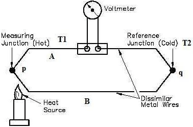
If the temperature of both the junctions is same, equal and opposite emf will be generated at both junctions and the net current flowing through the junction is zero. If the junctions are maintained at different temperatures, the emf’s will not become zero and there will be a net current flowing through the circuit. The total emf flowing through this circuit depends on the metals used within the circuit as well as the temperature of the two junctions. The total emf or the current flowing through the circuit can be measured easily by the suitable device.
The device for measuring the current or emf is connected within the circuit of the thermocouple. It measures the amount of emf flowing through the circuit due to the two junctions of the two dissimilar metals maintained at different temperatures. The two junctions of the thermocouple and the device used for measurement of emf (potentiometer) are shown.
Now, the temperature of the reference junctions is already known, while the temperature of measuring junction is unknown. The output obtained from the thermocouple circuit is calibrated directly against the unknown temperature. Thus the voltage or current output obtained from thermocouple circuit gives the value of unknown temperature directly.
Resistance Temperature Detectors
What are Resistance Temperature Detectors?
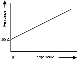
Resistance temperature detectors (RTD) are temperature sensors. They operate on the principle that the resistivity of a metal increases in proportion to its temperature.
A Platinum RTD uses platinum (Pt) for a resistance temperature sensing element, which has good temperature characteristics and is linear and stable.
Among the various types of temperature sensors, Platinum RTDs have been used widely with their high accuracy. In particular, Pt100 (resistance value at 0° is 100 ohm) has been popular worldwide. Nickel and copper are also used for RTDs. Thermistors are employed as resistors.
Three types of wiring techniques are available: two-wire, three-wire, and four-wire.
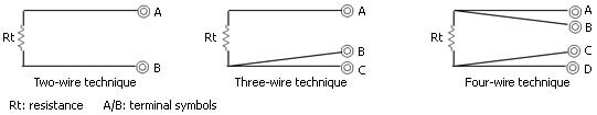
Moreover, a measuring circuit on the measuring instrument side differs depending on each wiring techniques. Figures illustrated below explain the principles of the three-wire technique most frequently used in the industrial measurement, and the four-wire technique used for precision measurements.
a) Principle of the three-wire technique
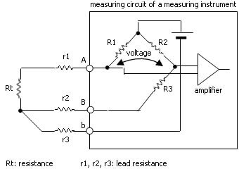
Lead resistance of r1 and r2 are perfectly matched, and therefore canceled in a bridge circuit. Therefore, keeping the resistance of the three leads low and uniform allows you to perform temperature measurements with few errors, even if the leads between Rt and the measuring instrument are made longer.
b) Principle of the four-wire technique
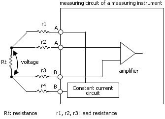
A constant current is passed through r1 and r4, and voltage is measured at the terminals of RTD, which is free from the effect of lead resistances in your measurement. Therefore, this system allows accurate temperature measurements.
If a RTD of the four-wire technique is connected to a measuring instrument of the three-wire technique, disenabling one of the RTD leads in the four-wire technique provides a simple configuration of temperature measurement. In this case, keeping the resistance of the three leads low and uniform is required in the same way as the three-wire technique. the unused lead must be terminated (insulated) to avoid the effects of noise and others.
Also Read: Thermocouple : Calculate Temperature from millivolts


Very good information
Thanks