Inst ToolsInst ToolsInst Tools
  • Courses
  • Automation
    • PLC
    • Control System
    • Safety System
    • Communication
    • Fire & Gas System
  • Instrumentation
    • Design
    • Pressure
    • Temperature
    • Flow
    • Level
    • Vibration
    • Analyzer
    • Control Valve
    • Switch
    • Calibration
    • Erection & Commissioning
  • Interview
    • Instrumentation
    • Electrical
    • Electronics
    • Practical
  • Q&A
    • Instrumentation
    • Control System
    • Electrical
    • Electronics
    • Analog Electronics
    • Digital Electronics
    • Power Electronics
    • Microprocessor
Search
  • Books
  • Software
  • Projects
  • Process
  • Tools
  • Basics
  • Formula
  • Power Plant
  • Root Cause Analysis
  • Electrical Basics
  • Animation
  • Standards
  • 4-20 mA Course
  • Siemens PLC Course
Reading: Why Do We Need to Connect Transformers in Parallel?
Share
Notification Show More
Font ResizerAa
Inst ToolsInst Tools
Font ResizerAa
  • Courses
  • Design
  • PLC
  • Interview
  • Control System
Search
  • Courses
  • Automation
    • PLC
    • Control System
    • Safety System
    • Communication
    • Fire & Gas System
  • Instrumentation
    • Design
    • Pressure
    • Temperature
    • Flow
    • Level
    • Vibration
    • Analyzer
    • Control Valve
    • Switch
    • Calibration
    • Erection & Commissioning
  • Interview
    • Instrumentation
    • Electrical
    • Electronics
    • Practical
  • Q&A
    • Instrumentation
    • Control System
    • Electrical
    • Electronics
    • Analog Electronics
    • Digital Electronics
    • Power Electronics
    • Microprocessor
Follow US
All rights reserved. Reproduction in whole or in part without written permission is prohibited.
Inst Tools > Blog > Electrical Basics > Why Do We Need to Connect Transformers in Parallel?

Why Do We Need to Connect Transformers in Parallel?

Learn why connecting transformers in parallel is important for load sharing, system reliability, and future expansion in power distribution.

Last updated: May 9, 2025 4:08 pm
Viral Nagda
Electrical Basics
No Comments
Share
6 Min Read
SHARE

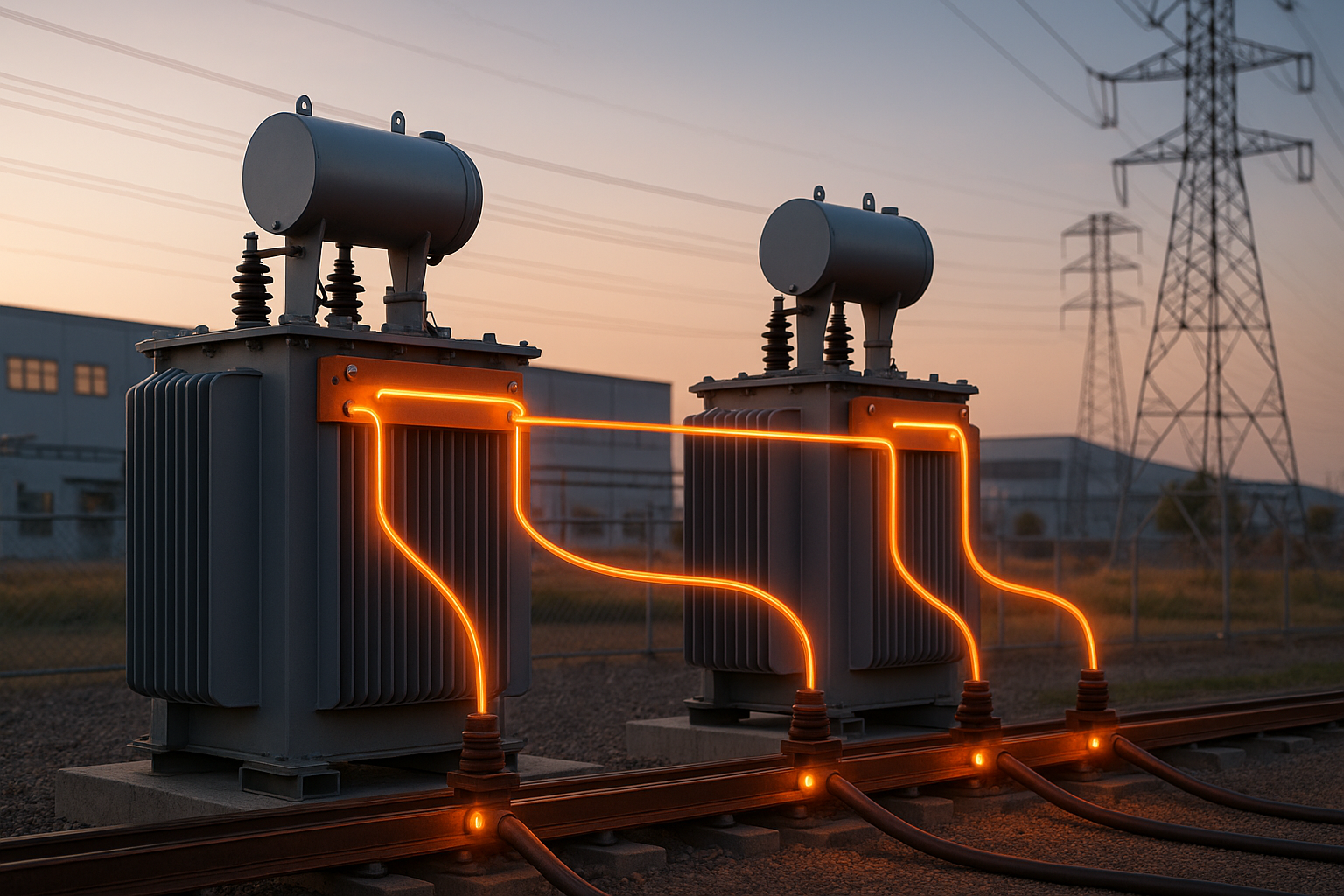
In electrical engineering, transformers are a very integral part of the design. Without them, the electrical supply cannot be given to a certain area. Often, engineers think of ways to optimize the use of transformers most efficiently. One such method is to connect transformers in parallel. This has been a proven way for a long time for efficient and reliable operation. Instead of using a single heavy load transformer, you can use smaller multiple load transformers. So why is this technology adopted? We will see in this post why we need to connect transformers in parallel.

Contents
Disadvantages of using a single transformerAdvantages of using multiple transformers in parallelFactors to consider when using multiple transformersTurns ratio:Phase sequence:Impedance:Vector group:

Disadvantages of using a single transformer

First of all, let us see why a single transformer concept can prove to be a disaster many times:

  1. The first-hand rule of using multiple objects is load sharing. So, using a single transformer cannot provide you the option of sharing loads in critical plants, and if it fails, the whole system will remain without power. Means, if you want to supply load to some non-critical areas, then too, you would have to run this single transformer, resulting in power wastage.
  2. Suppose you want to do some maintenance activities in the transformer; then shutting down the single transformer means shutting down the whole plant.
  3. A single transformer means a heavy rating one. Suppose the load has been reduced during offline working hours; the transformer will then run at a low capacity. Running a transformer below its rated capacity to a very low value results in no load losses (as the transformer is still consuming current from the primary side, resulting in magnetisation, but not exciting anywhere, which increases only magnetising current). This results in hysteresis loss and eddy current loss.

Advantages of using multiple transformers in parallel

So now, if we see the reverse criteria of the disadvantages, multiple transformers can play a handy role in the following way:

  1. When you have multiple transformers of the same capacity (meaning a single one is of 22 KV, then you can use two transformers of 11 KV each), then load sharing can be done. So, you can either use both the transformers for full load capacity, or use only one in case of low power requirement. This provides great flexibility in operation.
  2. Continuing the above point, you can shut down one transformer in case of any maintenance activity. The other one can supply a load, not full, but only to critical loads. The non-critical loads can remain off for a few hours according to your requirement.
  3. As multiple transformers mean a single transformer of a lower rating, no load loss occurring will be of a lower value than using a single heavy-rated transformer.
  4. Overall cost of maintenance, installation, and commissioning is reduced to a great extent in this setup and becomes very economical, instead of a single transformer.

Factors to consider when using multiple transformers

Why Do We Need to Connect Transformers in Parallel

Turns ratio:

The very first factor to consider is the voltage turns ratio. If the transformers have even a slight difference in their turns ratio, then it will result in circulating current flow in the circuit. Means, if one transformer has a secondary output of 220V and the other has 210V, both these transformers will try to impose their own voltages on the load, which is senseless. The resulting voltage difference of 10V will not go on the load and instead circulate between the transformers themselves. This will result in heating and energy loss.

Phase sequence:

This is the same as the concept for the turns ratio. If the voltage phase sequence for one transformer is different than the other, this will still increase the chances of short circuit or phase imbalance in the system. It can also cause an increase in heating and energy loss.

Impedance:

Impedance of the transformer is the internal resistance and reactance of the transformer. If the transformers have different impedances, then, for example, one transformer will resist more current, and the other will resist less current. The first one will thus pass less current to the load with reduced efficiency, and the second one will pass more current to the load with increased efficiency compared to the first one. Such an imbalance provides a circuit disruption in the load and hampers the performance of the system.

Vector group:

The last and most important factor is the vector group. The vector group tells us the type of winding connection (like star-delta) and the phase difference between primary and secondary. Similar to phase sequence, if the vector group varies, then it will result in a heavy circulation current in the system. This can either break down the system or halt the operation temporarily.

In this way, we saw why we need to connect transformers in parallel.

Read Next:

  • Why is IGBT used in VFD?
  • Auto Changeover Switch
  • SCADA in Power System
  • What is a Buchholz Relay?
  • Motor Winding Sensors

Don't Miss Our Updates
Be the first to get exclusive content straight to your email.
We promise not to spam you. You can unsubscribe at any time.
Invalid email address
You've successfully subscribed !

Continue Reading

Benefits of SIMOCODE over Intelligent MCC
Difference Between Permittivity and Permeability
What is Electrical Slip Ring? Principle, Types, Advantages, Applications
What is a Link Box?
What is Electrical Conduit? Types, Advantages, Disadvantages
Worldwide Voltage & Frequency Values
Share This Article
Facebook Whatsapp Whatsapp LinkedIn Copy Link
Share
Leave a Comment

Leave a Reply Cancel reply

Your email address will not be published. Required fields are marked *

Stay Connected

128.3kFollowersLike
69.1kFollowersFollow
208kSubscribersSubscribe
38kFollowersFollow

Categories

Explore More

Formula of AMP, KW, KVA, HP for AC and DC Voltages
What is an Instrument Transformer? – Types, Principle, Advantages
What is a Power Transformer? – Components and Types
Difference Between UL489 and UL1077
Geothermal Energy Power Plants
Pros and Cons of Soft Starter
Difference Between Isolator and Circuit Breaker
Electrical Power Grid Automation

Keep Learning

Hybrid Solar Power System

Difference Between Normal Inverter and Solar Inverter

Earth Fault

What are Ground Fault and Earth Fault?

Advantages of Star and Delta Systems

Advantages of Star and Delta Systems

Wiring Diagram Forward-Reverse for 3 Phase Motor

Motor Forward and Reverse Direction Control using Limit Switches

Fuse in a Electrical Circuit

Advantages & Disadvantages of Fuse in a Electrical Circuit

Top 10 Common Mistakes on Electrical Systems

Top 10 Common Mistakes on Electrical Systems

Humming Sound in Transformer

Why is the Humming Sound Produced in Transformer?

Technical Specification for Uninterrupted Power Supply (UPS) System

Technical Specification for Uninterrupted Power Supply (UPS) System

Learn More

diode-limiter-principle

Diode Limiters/Clippers Operation

Differential Pressure Switch Calibration Procedure - Copy

Differential Pressure Switch Calibration Procedure

Emergency Stop Push button

Emergency Stop Switch Spurious Trip

RSLogix5000 PLC Program Backup procedure

PLC Program for Conveyor System

PLC Conveyor Ladder Logic Program

Sensors and Transducers Classification

Sensors and Transducers Classification

Weir Diaphragm Valve

Diaphragm Valves Construction, Types, Stem & Bonnet Assembly

Digital Electronics Multiple Choice Questions

Erasable Programmable Read Only Memory Objective Questions

Follow US
All rights reserved. Reproduction in whole or in part without written permission is prohibited.
Welcome Back!

Sign in to your account

Username or Email Address
Password

Lost your password?