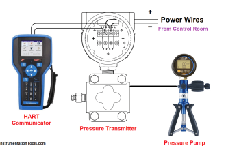
Capillary tubing provides a convenient method to separate a pressure instrument such as a gauge or transmitter from the actual process connection, allowing the instrument to be installed in a more accessible location.
However, users should be aware of the effects that capillary tubing has on the operation of the pressure sensing element.
Capillary tubing introduces three effects on the performance of pressure-sensing instruments:
1. Temperature effects
Temperature changes cause the liquid inside the capillary tube to expand and contract, changing the volume of the fill fluid.
The resulting error in the pressure reading is a function of the total volume of the tubing, pressure instrument, and isolator ring.
Because the rubber sleeve in the isolator ring has a much lower modulus of elasticity compared to a diaphragm seal, it can absorb most of the volumetric change resulting from temperature differences throughout the usable temperature range for isolator rings.
A typical error in gauge reading through a temperature swing from 0°F to 120°F is about ½ psi depending on isolator ring size and gauge type.
This is roughly a quarter the error expected with a standard 60 mm stainless steel diaphragm seal
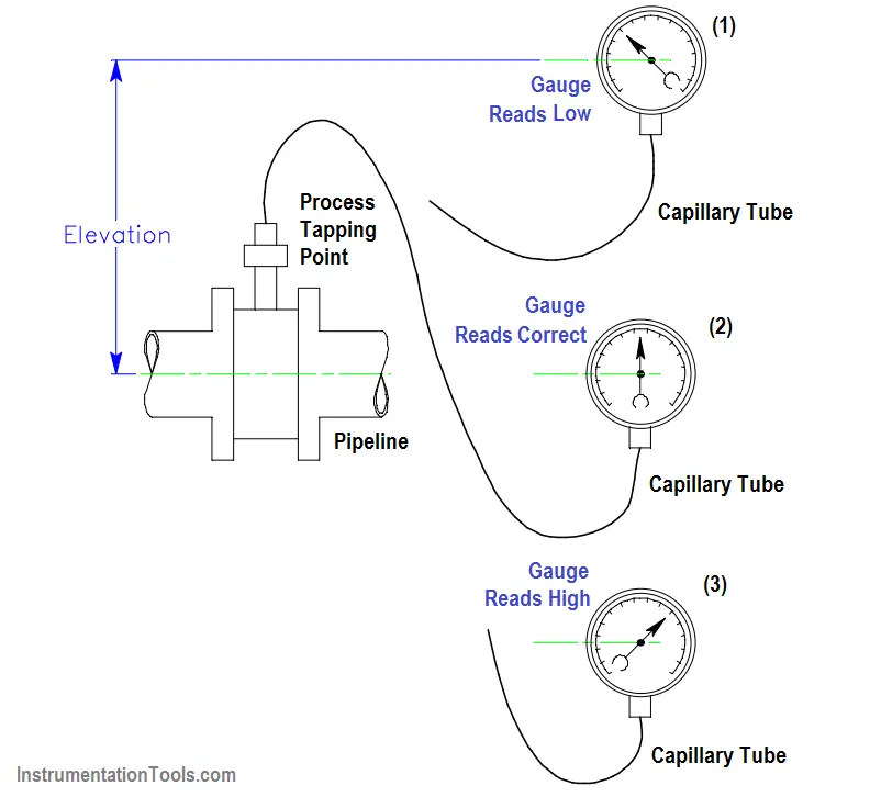
2. Elevation effects
As you change the elevation of the gauge with respect to the isolator ring, you introduce an elevation error. This error is due to the static pressure of the liquid in the capillary tube.
The change in gauge reading caused by elevation changes of the pressure sensing instrument can be calculated in advance using the following equation:

Our standard fill fluid is a silicone oil with a specific gravity = 0.967 at 77°F.
Observe polarity: If the gauge is above the isolator ring, then the elevation term in the above equation is positive; if the gauge is below the isolator ring, the elevation is negative.
If the gauge or transmitter has a zero adjust capability, the elevation error can be eliminated completely by re-setting the zero adjustment to compensate for the elevation change.
3. Response time
Capillary tubing introduces a response time lag in the instrument reading. This delayed reaction time is influenced by:
- Length of the capillary tube
- Internal diameter of the capillary tube
- Control volume of the pressure-sensing instrument
- Viscosity of the fill fluid, including temperature effects fill fluid viscosity
The control volume of a pressure-sensing instrument such as a gauge or transmitter is defined as the change in volume required to deflect the bourdon tube or sensing diaphragm from zero to 100% reading.
The smaller the control volume the better the performance. Instruments with smaller control volumes exhibit less temperature error and time lag than instruments with greater volume.
As a general rule, higher range instruments have a smaller control volume than lower range instruments; for example a 100-psi gauge has a much smaller control volume than a 15-psi gauge.
Another general rule is that electronically amplified devices have a smaller control volume than mechanical devices; again, to use an example, an electronic transmitter has about 1/100th the control volume of a bourdon tube gauge of the same range.
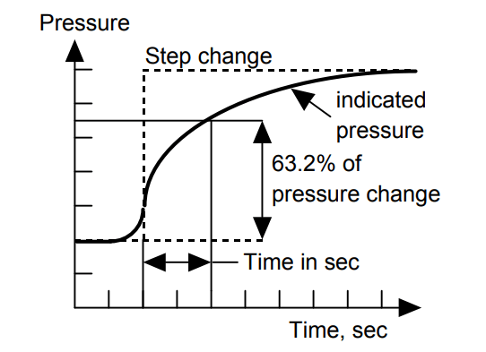
Response time is defined as the time, in seconds, for the pressure-sensing instrument to register 63.2% of a step change in pressure.
The reason the definition is not based on a 100% change is because, theoretically, it takes an infinite amount of time for any pressure-sensing instrument to respond to a step change in pressure.
That’s because the gauge pointer moves slower and slower as it gets closer to the actual pressure.
Author : David Gardellin, P. Eng, Onyx Valve Co