History of Variable Frequency Drives (VFD)
When Tesla first introduced the 3-phase alternating current (AC) induction motor in 1888, he knew that his invention was more efficient and reliable than Edison’s direct current (DC) motor. However, AC motor speed control requires either varying the magnetic flux or changing the number of poles on the motor. Even decades after the induction motor gained widespread use, changing the frequency for speed control remained an extremely difficult task — and the physical construction of the motor prevented manufacturers from creating motors with more than two speeds.
As a result, DC motors were necessary where accurate speed control and significant power output were required. In contrast to AC motor speed control requirements, DC motor speed control was achieved by inserting a rheostat into the low-power DC field circuit, which was feasible with available technology. These simple motor controls varied the speed and torque, and were the most economical way to do so for a number of decades.
By the 1980s, AC motor drive technology became reliable and inexpensive enough to compete with traditional DC motor control. These variable-frequency drives (VFDs) accurately control the speed of standard AC induction or synchronous motors. With VFDs, speed control with full torque is achieved from 0 rpm through the maximum rated speed and, if required, above the rated speed at reduced torque. VFDs manipulate the frequency of their output by rectifying an incoming AC current into DC, and then using voltage pulse-width modulation to recreate an AC current and voltage output waveform. However, this frequency conversion process causes 2% to 3% loss as heat in the VFD — caloric energy that must be dissipated. The process also yields overvoltage spikes and harmonic current distortions.
Types of Variable Frequency Drive
There are three common types of VFDs. Current source inversion (CSI) has been successfully used in signal processing and industrial power applications. CSI VFDs are the only type that has regenerative power capability. In other words, they can absorb power flow back from the motor into the power supply. CSI VFDs give a very clean current waveform but require large, expensive inductors in their construction and cause cogging (pulsating movement during rotation) below 6 Hz.
Voltage source inversion (VSI) drives have poor power factor, can cause motor cogging below 6 Hz, and are non-regenerative. Consequently, CSI and VSI drives have not been widely used.
Pulse-width modulation (PWM) VFDs are most commonly used in industry because of excellent input power factor due to fixed DC bus voltage, no motor cogging, higher efficiencies, and lower cost. A PWM VFD uses a series of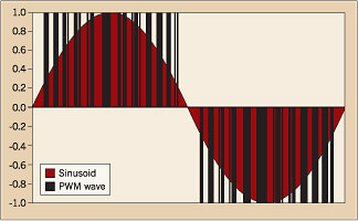 voltage pulses of different lengths to simulate a sinusoidal wave. Ideally, the pulses are timed so that the time average integral of the drive yields a perfect sinusoid. The current method of choice to produce this waveform runs a triangle wave and sine wave through a comparator, and outputs a voltage pulse whenever the sine wave’s value is greater than the triangle wave. The current electric component of choice to generate the voltage pulse is the insulated gate bipolar transistor (IGBT), although silicon-controlled rectifiers (SCRs) can work as well. In the near future, injection-enhanced gate transistors (IEGTs) will be used to perform this task. Much more long term, memristors will probably become the component of choice for this task.
Basics of Variable Frequency Drives:
What is a VFD?
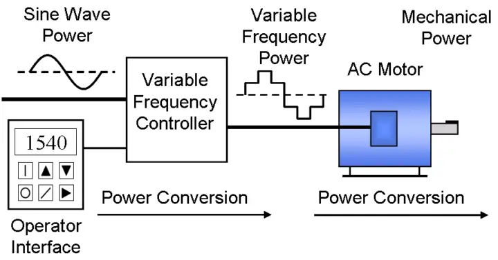
A Variable Frequency Drive (VFD) is a type of motor controller that drives an electric motor by varying the frequency and voltage supplied to the electric motor. Other names for a VFD are variable speed drive,adjustable speed drive, adjustable frequency drive, AC drive,microdrive, and inverter.
Frequency (or hertz) is directly related to the motor’s speed (RPMs). In other words, the faster the frequency, the faster the RPMs go. If an application does not require an electric motor to run at full speed, the VFD can be used to ramp down the frequency and voltage to meet the requirements of the electric motor’s load. As the application’s motor speed requirements change, the VFD can simply turn up or down the motor speed to meet the speed requirement.
How does a Variable Frequency Drive work?
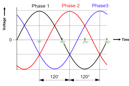
The first stage of a Variable Frequency AC Drive, or VFD, is the Converter. The converter is comprised of six diodes, which are similar to check valves used in plumbing systems. They allow current to flow in only one direction; the direction shown by the arrow in the diode symbol. For example, whenever A-phase voltage (voltage is similar to pressure in plumbing systems) is more positive than B or C phase voltages, then that diode will open and allow current to flow. When B-phase becomes more positive than A-phase, then the B-phase diode will open and the A-phase diode will close. The same is true for the 3 diodes on the negative side of the bus. Thus, we get six current “pulses” as each diode opens and closes. This is called a “six-pulse VFD”, which is the standard configuration for current Variable Frequency Drives.
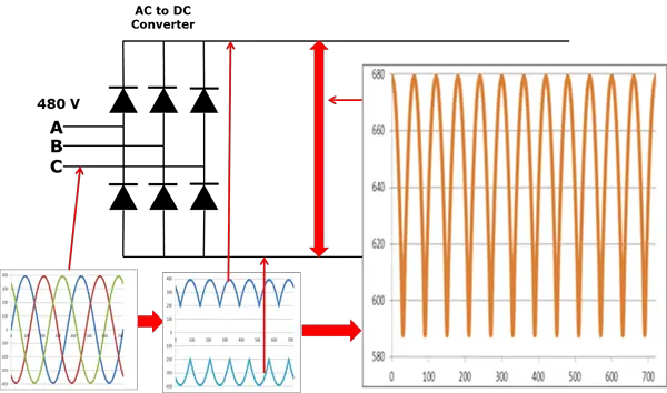
Let us assume that the drive is operating on a 480V power system. The 480V rating is “rms” or root-mean-squared. The peaks on a 480V system are 679V. As you can see, the VFD dc bus has a dc voltage with an AC ripple. The voltage runs between approximately 580V and 680V.
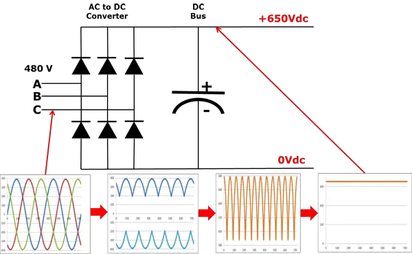
We can get rid of the AC ripple on the DC bus by adding a capacitor. A capacitor operates in a similar fashion to a reservoir or accumulator in a plumbing system. This capacitor absorbs the ac ripple and delivers a smooth dc voltage. The AC ripple on the DC bus is typically less than 3 Volts. Thus, the voltage on the DC bus becomes “approximately” 650VDC. The actual voltage will depend on the voltage level of the AC line feeding the drive, the level of voltage unbalance on the power system, the motor load, the impedance of the power system, and any reactors or harmonic filters on the drive.
The diode bridge converter that converts AC-to-DC, is sometimes just referred to as a converter. The converter that converts the dc back to ac is also a converter, but to distinguish it from the diode converter, it is usually referred to as an “inverter”. It has become common in the industry to refer to any DC-to-AC converter as an inverter.
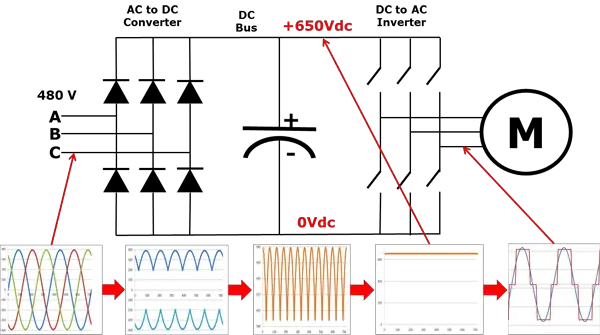
Note that in a real VFD, the switches shown would actually be transistors or thyristors.
When we close one of the top switches in the inverter, that phase of the motor is connected to the positive dc bus and the voltage on that phase becomes positive. When we close one of the bottom switches in the converter, that phase is connected to the negative dc bus and becomes negative. Thus, we can make any phase on the motor become positive or negative at will and can thus generate any frequency that we want. So, we can make any phase be positive, negative, or zero.
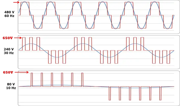
The blue sine-wave is shown for comparison purposes only. The drive does not generate this sine wave.
Notice that the output from the VFD is a “rectangular” wave form. VFD’s do not produce a sinusoidal output. This rectangular waveform would not be a good choice for a general purpose distribution system, but is perfectly adequate for a motor.
If we want to reduce the motor frequency to 30 Hz, then we simply switch the inverter output transistors more slowly. But, if we reduce the frequency to 30Hz, then we must also reduce the voltage to 240V in order to maintain the V/Hz ratio. How are we going to reduce the voltage if the only voltage we have is 650VDC?
This is called Pulse Width Modulation or PWM. Imagine that we could control the pressure in a water line by turning the valve on and off at a high rate of speed. While this would not be practical for plumbing systems, it works very well for VFD’s. Notice that during the first half cycle, the voltage is ON half the time and OFF half the time. Thus, the average voltage is half of 480V or 240V. By pulsing the output, we can achieve any average voltage on the output of the VFD.
Why should I use a VFD?
Reduce Energy Consumption and Energy Costs
If you have an application that does not need to be run at full speed, then you can cut down energy costs by controlling the motor with a variable frequency drive, which is one of the benefits of Variable Frequency Drives. VFDs allow you to match the speed of the motor-driven equipment to the load requirement. There is no other method of AC electric motor control that allows you to accomplish this.
Electric motor systems are responsible for more than 65% of the power consumption in industry today. Optimizing motor control systems by installing or upgrading to VFDs can reduce energy consumption in your facility by as much as 70%. Additionally, the utilization of VFDs improves product quality, and reduces production costs. Combining energy efficiency tax incentives, and utility rebates, returns on investment for VFD installations can be as little as 6 months.
Increase Production Through Tighter Process Control
By operating your motors at the most efficient speed for your application, fewer mistakes will occur, and thus, production levels will increase, which earns your company higher revenues. On conveyors and belts you eliminate jerks on start-up allowing high through put.
Extend Equipment Life and Reduce Maintenance
Your equipment will last longer and will have less downtime due to maintenance when it’s controlled by VFDs ensuring optimal motor application speed. Because of the VFDs optimal control of the motor’s frequency and voltage, the VFD will offer better protection for your motor from issues such as electro thermal overloads, phase protection, under voltage, overvoltage, etc.. When you start a load with a VFD you will not subject the motor or driven load to the “instant shock” of across the line starting, but can start smoothly, thereby eliminating belt, gear and bearing wear. It also is an excellent way to reduce and/or eliminate water hammer since we can have smooth acceleration and deceleration cycles.
Also Read: Electrical Basics & Theory


How to make star and delta connections and for what purpose ?
Hello Vishal, Basics of Star & Delta Connections article Posted in Electrical Category. Thanks
thanks for this helpfull post .now we better understand about drives
how much power safe vfd calculation give
VERY VERY USEFUL INFORMATION
This was so helpful in my preparation for something later today. Thanks for the great information.
Hi there! From a single phase 230v inverter what is the three phase output? Can i take 380v between phases to the output?
From a single phase 230v inverter the three phase output will be 230v
very nice under standing of star and delta and with v f d application.
SIR ,Suggest some PLC books for beginner .
Sir,
could you clarify me the following?
If we use VFD as suggested, can be convert 2 phase into 3 phase electric supply to use for Brick wire cutting machine system.
thanks and regards,