A third variation (Tracking ADC) on the counter-DAC-based converter theme is, in my estimation, the most elegant. Instead of a regular “up” counter driving the DAC, this circuit uses an up/down counter.
The counter is continuously clocked, and the up/down control line is driven by the output of the comparator. So, when the analog input signal exceeds the DAC output, the counter goes into the “count up” mode.
When the DAC output exceeds the analog input, the counter switches into the “count down” mode. Either way, the DAC output always counts in the proper direction to track the input signal.
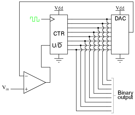
Notice how no shift register is needed to buffer the binary count at the end of a cycle.
Since the counter\’s output continuously tracks the input (rather than counting to meet the input and then resetting back to zero), the binary output is legitimately updated with every clock pulse.
An advantage of this converter circuit is speed, since the counter never has to reset. Note the behavior of this circuit:
Note the much faster update time than any of the other “counting” ADC circuits. Also note how at the very beginning of the plot where the counter had to “catch up” with the analog signal, the rate of change for the output was identical to that of the first counting ADC.
Also, with no shift register in this circuit, the binary output would actually ramp up rather than jump from zero to an accurate count as it did with the counter and successive approximation ADC circuits.
Perhaps the greatest drawback to this ADC design is the fact that the binary output is never stable: it always switches between counts with every clock pulse, even with a perfectly stable analog input signal. This phenomenon is informally known as bit bobble, and it can be problematic in some digital systems.
This tendency can be overcome, though, through the creative use of a shift register. For example, the counter\’s output may be latched through a parallel-in/parallel-out shift register only when the output changes by two or more steps. Building a circuit to detect two or more successive counts in the same direction takes a little ingenuity, but is worth the effort.
Initially, AC motors were constructed like DC motors. Numerous problems were encountered due to changing…
Learn about the AC Instrumentation Transducers like Potentiometer, LVDT, RVDT, Synchro, and Capacitive Transducers.
AC bridge circuit unknown impedance is balanced by a standard impedance of similar type on…
Power Quality is the general term given to represent an AC power system freedom from harmonic…
Hall effect - Voltage is proportional to current and strength of the perpendicular magnetic field.…
Learn about the Frequency and Phase Measurement from our free online electronics and electrical engineering…

