We can trace the direction that electrons will flow in the same circuit by starting at the negative (-) terminal and following through to the positive (+) terminal of the battery, the only source of voltage in the circuit.
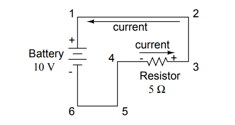
From this we can see that the electrons are moving counter-clockwise, from point 6 to 5 to 4 to 3 to 2 to 1 and back to 6 again. As the current encounters the 5 Ω resistance, voltage is dropped across the resistor’s ends. The polarity of this voltage drop is negative (-) at point 4 with respect to positive (+) at point 3.
We can mark the polarity of the resistor’s voltage drop with these negative and positive symbols, in accordance with the direction of current (whichever end of the resistor the current is entering is negative with respect to the end of the resistor it is exiting:
We could make our table of voltages a little more complete by marking the polarity of the voltage for each pair of points in this circuit:
While it might seem a little silly to document polarity of voltage drop in this circuit, it is an important concept to master. It will be critically important in the analysis of more complex circuits involving multiple resistors and/or batteries.
It should be understood that polarity has nothing to do with Ohm’s Law: there will never be negative voltages, currents, or resistance entered into any Ohm’s Law equations! There are other mathematical principles of electricity that do take polarity into account through the use of signs (+ or -), but not Ohm’s Law.
Initially, AC motors were constructed like DC motors. Numerous problems were encountered due to changing…
Learn about the AC Instrumentation Transducers like Potentiometer, LVDT, RVDT, Synchro, and Capacitive Transducers.
AC bridge circuit unknown impedance is balanced by a standard impedance of similar type on…
Power Quality is the general term given to represent an AC power system freedom from harmonic…
Hall effect - Voltage is proportional to current and strength of the perpendicular magnetic field.…
Learn about the Frequency and Phase Measurement from our free online electronics and electrical engineering…
