A peak detector is a series connection of a diode and a capacitor outputting a DC voltage equal to the peak value of the applied AC signal.
The circuit is shown in Figure below with the corresponding SPICE net list. An AC voltage source applied to the peak detector, charges the capacitor to the peak of the input.
The diode conducts positive “half cycles,” charging the capacitor to the waveform peak. When the input waveform falls below the DC “peak” stored on the capacitor, the diode is reverse biased, blocking current flow from capacitor back to the source.
Thus, the capacitor retains the peak value even as the waveform drops to zero. Another view of the peak detector is that it is the same as a half-wave rectifier with a filter capacitor added to the output.
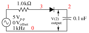 | *SPICE 03441.eps C1 2 0 0.1u R1 1 3 1.0k V1 1 0 SIN(0 5 1k) D1 3 2 diode .model diode d .tran 0.01m 50mm .end |
Peak detector: Diode conducts on positive half cycles charging capacitor to the peak voltage (less diode forward drop).
It takes a few cycles for the capacitor to charge to the peak as in Figure below due to the series resistance (RC “time constant”). Why does the capacitor not charge all the way to 5 V? It would charge to 5 V if an “ideal diode” were obtainable. However, the silicon diode has a forward voltage drop of 0.7 V which subtracts from the 5 V peak of the input.
Peak detector: Capacitor charges to peak within a few cycles.
The circuit in Figure above could represent a DC power supply based on a half-wave rectifier. The resistance would be a few Ohms instead of 1 kΩ due to a transformer secondary winding replacing the voltage source and resistor. A larger “filter” capacitor would be used.
A power supply based on a 60 Hz source with a filter of a few hundred µF could supply up to 100 mA. Half-wave supplies seldom supply more due to the difficulty of filtering a half-wave.
The peak detector may be combined with other components to build a crystal radio.
Initially, AC motors were constructed like DC motors. Numerous problems were encountered due to changing…
Learn about the AC Instrumentation Transducers like Potentiometer, LVDT, RVDT, Synchro, and Capacitive Transducers.
AC bridge circuit unknown impedance is balanced by a standard impedance of similar type on…
Power Quality is the general term given to represent an AC power system freedom from harmonic…
Hall effect - Voltage is proportional to current and strength of the perpendicular magnetic field.…
Learn about the Frequency and Phase Measurement from our free online electronics and electrical engineering…

