Let\’s take the same components for our series example circuit and connect them in parallel: (Figure below)
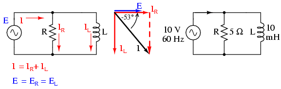
Parallel R-L circuit.
Because the power source has the same frequency as the series example circuit, and the resistor and inductor both have the same values of resistance and inductance, respectively, they must also have the same values of impedance. So, we can begin our analysis table with the same “given” values:
The only difference in our analysis technique this time is that we will apply the rules of parallel circuits instead of the rules for series circuits. The approach is fundamentally the same as for DC. We know that voltage is shared uniformly by all components in a parallel circuit, so we can transfer the figure of total voltage (10 volts ∠ 0o) to all components columns:
Now we can apply Ohm\’s Law (I=E/Z) vertically to two columns of the table, calculating current through the resistor and current through the inductor:
Just as with DC circuits, branch currents in a parallel AC circuit add to form the total current (Kirchhoff\’s Current Law still holds true for AC as it did for DC):
Finally, total impedance can be calculated by using Ohm\’s Law (Z=E/I) vertically in the “Total” column. Incidentally, parallel impedance can also be calculated by using a reciprocal formula identical to that used in calculating parallel resistances.
The only problem with using this formula is that it typically involves a lot of calculator keystrokes to carry out. And if you\’re determined to run through a formula like this “longhand,” be prepared for a very large amount of work! But, just as with DC circuits, we often have multiple options in calculating the quantities in our analysis tables, and this example is no different.
No matter which way you calculate total impedance (Ohm\’s Law or the reciprocal formula), you will arrive at the same figure:
REVIEW:
Initially, AC motors were constructed like DC motors. Numerous problems were encountered due to changing…
Learn about the AC Instrumentation Transducers like Potentiometer, LVDT, RVDT, Synchro, and Capacitive Transducers.
AC bridge circuit unknown impedance is balanced by a standard impedance of similar type on…
Power Quality is the general term given to represent an AC power system freedom from harmonic…
Hall effect - Voltage is proportional to current and strength of the perpendicular magnetic field.…
Learn about the Frequency and Phase Measurement from our free online electronics and electrical engineering…


