Using the same value components in our series example circuit, we will connect them in parallel and see what happens: (Figure below)
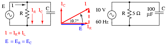
Because the power source has the same frequency as the series example circuit, and the resistor and capacitor both have the same values of resistance and capacitance, respectively, they must also have the same values of impedance. So, we can begin our analysis table with the same “given” values:
This being a parallel circuit now, we know that voltage is shared equally by all components, so we can place the figure for total voltage (10 volts ∠ 0o) in all the columns:
Now we can apply Ohm\’s Law (I=E/Z) vertically to two columns in the table, calculating current through the resistor and current through the capacitor:
Just as with DC circuits, branch currents in a parallel AC circuit add up to form the total current (Kirchhoff\’s Current Law again):
Finally, total impedance can be calculated by using Ohm\’s Law (Z=E/I) vertically in the “Total” column. As we saw in the AC inductance chapter, parallel impedance can also be calculated by using a reciprocal formula identical to that used in calculating parallel resistances. It is noteworthy to mention that this parallel impedance rule holds true regardless of the kind of impedances placed in parallel.
In other words, it doesn\’t matter if we\’re calculating a circuit composed of parallel resistors, parallel inductors, parallel capacitors, or some combination thereof: in the form of impedances (Z), all the terms are common and can be applied uniformly to the same formula. Once again, the parallel impedance formula looks like this:
The only drawback to using this equation is the significant amount of work required to work it out, especially without the assistance of a calculator capable of manipulating complex quantities.
Regardless of how we calculate total impedance for our parallel circuit (either Ohm\’s Law or the reciprocal formula), we will arrive at the same figure:
REVIEW:
Initially, AC motors were constructed like DC motors. Numerous problems were encountered due to changing…
Learn about the AC Instrumentation Transducers like Potentiometer, LVDT, RVDT, Synchro, and Capacitive Transducers.
AC bridge circuit unknown impedance is balanced by a standard impedance of similar type on…
Power Quality is the general term given to represent an AC power system freedom from harmonic…
Hall effect - Voltage is proportional to current and strength of the perpendicular magnetic field.…
Learn about the Frequency and Phase Measurement from our free online electronics and electrical engineering…


