Connecting digital circuitry to sensor devices is simple if the sensor devices are inherently digital themselves. Switches, relays, and encoders are easily interfaced with gate circuits due to the on/off nature of their signals.
However, when analog devices are involved, interfacing becomes much more complex. What is needed is a way to electronically translate analog signals into digital (binary) quantities, and vice versa. An analog-to-digital converter, or ADC, performs the former task while a digital-to-analog converter, or DAC, performs the latter.
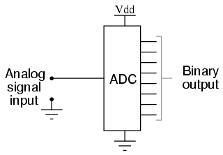
An ADC inputs an analog electrical signal such as voltage or current and outputs a binary number. In block diagram form, it can be represented as such:
A DAC, on the other hand, inputs a binary number and outputs an analog voltage or current signal. In block diagram form, it looks like this:
Together, they are often used in digital systems to provide the complete interface with analog sensors and output devices for control systems such as those used in automotive engine controls:
It is much easier to convert a digital signal into an analog signal than it is to do the reverse. Therefore, we will begin with DAC circuitry and then move to ADC circuitry.
Initially, AC motors were constructed like DC motors. Numerous problems were encountered due to changing…
Learn about the AC Instrumentation Transducers like Potentiometer, LVDT, RVDT, Synchro, and Capacitive Transducers.
AC bridge circuit unknown impedance is balanced by a standard impedance of similar type on…
Power Quality is the general term given to represent an AC power system freedom from harmonic…
Hall effect - Voltage is proportional to current and strength of the perpendicular magnetic field.…
Learn about the Frequency and Phase Measurement from our free online electronics and electrical engineering…


