A demultiplexer, sometimes abbreviated dmux, is a circuit that has one input and more than one output. It is used when a circuit wishes to send a signal to one of many devices.
This description sounds similar to the description given for a decoder, but a decoder is used to select among many devices while a demultiplexer is used to send a signal among many devices.
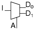
A demultiplexer is used often enough that it has its own schematic symbol
The truth table for a 1-to-2 demultiplexer is
Using our 1-to-2 decoder as part of the circuit, we can express this circuit easily
This circuit can be expanded two different ways. You can increase the number of signals that get transmitted, or you can increase the number of inputs that get passed through.
To increase the number of inputs that get passed through just requires a larger line decoder. Increasing the number of signals that get transmitted is even easier.
As an example, a device that passes one set of two signals among four signals is a “two-bit 1-to-2 demultiplexer”. Its circuit is
or by expressing the circuit as
shows that it could be two one-bit 1-to-2 demultiplexers without changing its expected behavior.
A 1-to-4 demultiplexer can easily be built from 1-to-2 demultiplexers as follows.
Initially, AC motors were constructed like DC motors. Numerous problems were encountered due to changing…
Learn about the AC Instrumentation Transducers like Potentiometer, LVDT, RVDT, Synchro, and Capacitive Transducers.
AC bridge circuit unknown impedance is balanced by a standard impedance of similar type on…
Power Quality is the general term given to represent an AC power system freedom from harmonic…
Hall effect - Voltage is proportional to current and strength of the perpendicular magnetic field.…
Learn about the Frequency and Phase Measurement from our free online electronics and electrical engineering…


