Since the enable input on a gated S-R latch provides a way to latch the Q and not-Q outputs without regard to the status of S or R, we can eliminate one of those inputs to create a multivibrator latch circuit with no “illegal” input states. Such a circuit is called a D latch, and its internal logic looks like this:
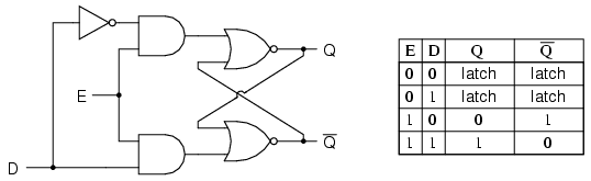
Note that the R input has been replaced with the complement (inversion) of the old S input, and the S input has been renamed to D.
As with the gated S-R latch, the D latch will not respond to a signal input if the enable input is 0—it simply stays latched in its last state. When the enable input is 1, however, the Q output follows the D input.
Since the R input of the S-R circuitry has been done away with, this latch has no “invalid” or “illegal” state. Q and not-Q are always opposite of one another. If the above diagram is confusing at all, the next diagram should make the concept simpler:
Like both the S-R and gated S-R latches, the D latch circuit may be found as its own prepackaged circuit, complete with a standard symbol:
The D latch is nothing more than a gated S-R latch with an inverter added to make R the complement (inverse) of S.
Let’s explore the ladder logic equivalent of a D latch, modified from the basic ladder diagram of an S-R latch:
An application for the D latch is a 1-bit memory circuit. You can “write” (store) a 0 or 1 bit in this latch circuit by making the enable input high (1) and setting D to whatever you want the stored bit to be.
When the enable input is made low (0), the latch ignores the status of the D input and merrily holds the stored bit value, outputting at the stored value at Q, and its inverse on output not-Q.
Summary
A D latch is like an S-R latch with only one input: the “D” input. Activating the D input sets the circuit, and de-activating the D input resets the circuit. Of course, this is only if the enable input (E) is activated as well. Otherwise, the output(s) will be latched, unresponsive to the state of the D input.
D latches can be used as 1-bit memory circuits, storing either a “high” or a “low” state when disabled, and “reading” new data from the D input when enabled.
Initially, AC motors were constructed like DC motors. Numerous problems were encountered due to changing…
Learn about the AC Instrumentation Transducers like Potentiometer, LVDT, RVDT, Synchro, and Capacitive Transducers.
AC bridge circuit unknown impedance is balanced by a standard impedance of similar type on…
Power Quality is the general term given to represent an AC power system freedom from harmonic…
Hall effect - Voltage is proportional to current and strength of the perpendicular magnetic field.…
Learn about the Frequency and Phase Measurement from our free online electronics and electrical engineering…


