Let’s begin with a semiconductor gate circuit in need of simplification. The “A,” “B,” and “C” input signals are assumed to be provided from switches, sensors, or perhaps other gate circuits. Where these signals originate is of no concern in the task of gate reduction.
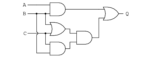
Our first step in simplification must be to write a Boolean expression for this circuit. This task is easily performed step by step if we start by writing sub-expressions at the output of each gate, corresponding to the respective input signals for each gate.
Remember that OR gates are equivalent to Boolean addition, while AND gates are equivalent to Boolean multiplication.
For example, I’ll write sub-expressions at the outputs of the first three gates:
Finally, the output (“Q”) is seen to be equal to the expression AB + BC(B + C):
The final expression, B(A + C), is much simpler than the original, yet performs the same function. If you would like to verify this, you may generate a truth table for both expressions and determine Q’s status (the circuits’ output) for all eight logic-state combinations of A, B, and C, for both circuits. The two truth tables should be identical.
Now, we must generate a schematic diagram from this Boolean expression. To do this, evaluate the expression, following proper mathematical order of operations (multiplication before addition, operations inside parentheses before anything else), and draw gates for each step.
Remember again that OR gates are equivalent to Boolean addition, while AND gates are equivalent to Boolean multiplication. In this case, we would begin with the sub-expression “A + C”, which is an OR gate:
The next step in evaluating the expression “B(A + C)” is to multiply (AND gate) the signal B by the output of the previous gate (A + C):
Electromechanical relay circuits, typically being slower, consuming more electrical power to operate, costing more, and having a shorter average life than their semiconductor counterparts, benefit dramatically from Boolean simplification. Let’s consider an example circuit:
As before, our first step in reducing this circuit to its simplest form must be to develop a Boolean expression from the schematic. The easiest way I’ve found to do this is to follow the same steps I’d normally follow to reduce a series-parallel resistor network to a single, total resistance.
For example, examine the following resistor network with its resistors arranged in the same connection pattern as the relay contacts in the former circuit, and corresponding total resistance formula:
Write a Boolean expression for this relay contact circuit, following the same order of precedence that you would follow in reducing a series-parallel resistor network to a total resistance.
It may be helpful to write a Boolean sub-expression to the left of each ladder “rung,” to help organize your expression-writing:
To convert a gate circuit to a Boolean expression, label each gate output with a Boolean sub-expression corresponding to the gates’ input signals, until a final expression is reached at the last gate.
To convert a Boolean expression to a gate circuit, evaluate the expression using standard order of operations: multiplication before addition, and operations within parentheses before anything else.
To convert a ladder logic circuit to a Boolean expression,each rung with a Boolean sub-expression corresponding to the contacts’ input signals, until a final expression is reached at the last coil or light.
To determine proper order of evaluation, treat the contacts as though they were resistors, and as if you were determining total resistance of the series-parallel network formed by them. In other words, look for contacts that are either directly in series or directly in parallel with each other first, then “collapse” them into equivalent Boolean sub-expressions before proceeding to other contacts.
To convert a Boolean expression to a ladder logic circuit, evaluate the expression using standard order of operations: multiplication before addition, and operations within parentheses before anything else.
Initially, AC motors were constructed like DC motors. Numerous problems were encountered due to changing…
Learn about the AC Instrumentation Transducers like Potentiometer, LVDT, RVDT, Synchro, and Capacitive Transducers.
AC bridge circuit unknown impedance is balanced by a standard impedance of similar type on…
Power Quality is the general term given to represent an AC power system freedom from harmonic…
Hall effect - Voltage is proportional to current and strength of the perpendicular magnetic field.…
Learn about the Frequency and Phase Measurement from our free online electronics and electrical engineering…


