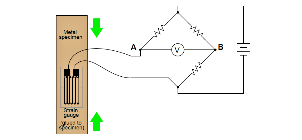
A strain gauge is a device used to measure the strain (compression or expansion) of a solid object by producing a resistance change proportional to the amount of strain.
As the gauge is strained, its electrical resistance alters slightly:
Strain Gauge
Explain why the electrical resistance of a strain gauge changes as it stretches and shrinks, and also correlate the direction of resistance change (more or less) with the direction of applied force.
As a strain gauge is stretched, its conductors become longer and thinner, thus increasing resistance. As a strain gauge is compressed, its conductors become shorter and fatter, thus decreasing resistance. The bridge circuit becomes more unbalanced as the strain gauge’s resistance changes from the neutral (resting) value.
The following strain gauge is shown connected in a “quarter-bridge” circuit (meaning only one-quarter of the bridge actively senses strain, while the other three-quarters of the bridge are fixed in resistance):
Explain what would happen to the voltage measured across this bridge circuit (VAB) if the strain gauge were to be compressed, assuming that the bridge begins in a balanced condition with no strain on the gauge.
In this circuit, voltage drop across the strain gauge decreases as it is compressed. This causes the potential at point A to become more negative, resulting in VAB developing with A negative and B positive.
Share your answers with us through below comments section.
Read Next:
- Basics of Strain Gauges
- Strain Gauge Load Cell
- Optical Data Communication
- Gas Sensor Principle
- Strain Gauge Accelerometer
Credits: Tony Kuphaldt

