Inst ToolsInst ToolsInst Tools
  • Courses
  • Videos
  • Q & A
    • Interview
      • Instrumentation
      • Electronics
      • Electrical
      • Practical Questions
    • MCQ
      • Instrumentation MCQ
      • Electrical MCQ
      • Electronics MCQ
      • Control Systems MCQ
      • Analog Electronics MCQ
      • Digital Electronics MCQ
      • Power Electronics MCQ
      • Microprocessor MCQ
      • Multiple Choice Questions
  • EE
    • Electronics
      • Electronics Q & A
      • Electronic Basics
      • Electronic Devices & Circuits
      • Electronics Animation
      • Digital Electronics
    • Electrical
      • Electrical Basics
      • Electrical Q & A
      • Power Electronics
      • Electrical Machines
      • Electrical Animation
      • Power Systems
      • Switchgear & Protection
      • Transmission & Distribution
  • Measure
    • Control Valves
    • Calibration
    • Temperature
    • Pressure
    • Flow
    • Level
    • Analyzers
    • Switches
    • Vibration
    • Solenoid Valve
  • Control
    • PLC Tutorials
    • Control Systems
    • Safety Instrumented System (SIS)
    • Communication
    • Fire & Gas System
  • More
    • Design
    • Tools
    • Animation
    • Basics
    • Formulas
    • Standards
    • TextBooks
    • Common
    • Software
    • Excel Tools
    • Erection & Commissioning
    • Process Fundamentals
    • Videos
    • Books
Search
All rights reserved. Reproduction in whole or in part without written permission is prohibited.
Reading: Harmonics effect on Transformer
Share
Notification Show More
Font ResizerAa
Inst ToolsInst Tools
Font ResizerAa
  • Courses
  • PLC Tutorials
  • Control Systems
Search
  • Courses
  • Videos
  • Q & A
    • Interview
    • MCQ
  • EE
    • Electronics
    • Electrical
  • Measure
    • Control Valves
    • Calibration
    • Temperature
    • Pressure
    • Flow
    • Level
    • Analyzers
    • Switches
    • Vibration
    • Solenoid Valve
  • Control
    • PLC Tutorials
    • Control Systems
    • Safety Instrumented System (SIS)
    • Communication
    • Fire & Gas System
  • More
    • Design
    • Tools
    • Animation
    • Basics
    • Formulas
    • Standards
    • TextBooks
    • Common
    • Software
    • Excel Tools
    • Erection & Commissioning
    • Process Fundamentals
    • Videos
    • Books
Follow US
All rights reserved. Reproduction in whole or in part without written permission is prohibited.
Inst Tools > Blog > Power Systems > Harmonics effect on Transformer

Harmonics effect on Transformer

Last updated: September 19, 2016 5:00 am
Editorial Staff
Power Systems
No Comments
Share
1 Min Read
SHARE

Harmonics distortion effect on Power System and their impact on Induction Motors are already discussed.

Some of the disadvantages of harmonics and their impact on the transformers are:

  • RMS current increase
  • Eddy Current loss increases
  • DC offset current saturation

RMS current Increase:

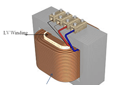
Harmonics currents in the system will increase the RMS current in the transformers. This increase in the RMS current will increase the losses (copper losses) in the transformer which results in the reduction of the overall efficiency of the transformer

Eddy Current Loss Increase:

Eddy currents loss is proportional to the square of the applied frequency. As the harmonic components will have the frequencies of the order of multiples of the fundamental frequency eddy current losses will increase with the presence of the harmonic components in the current and voltage waveforms. Therefore because of the increase in the eddy current loss overall efficiency of the transformer comes down. Harmonic component also increase the temperature of the windings.

DC offset current saturation:

Due to the presence of dc component in the harmonics tend to saturate the core of the transformer.

Don't Miss Our Updates
Be the first to get exclusive content straight to your email.
We promise not to spam you. You can unsubscribe at any time.
Invalid email address
You've successfully subscribed !

Continue Reading

Silicon Carbide Lightning Arresters Working Principle
Ferroresonance in Power Transformers
Advantages & Disadvantages of AC power and DC power
Power System Protection Multiple Choice Questions
Advantages and Disadvantages of Per Unit System
Rotor Angle Stability of Synchronous Generators in Power System
Share This Article
Facebook Whatsapp Whatsapp LinkedIn Copy Link
Share
Leave a Comment

Leave a Reply Cancel reply

Your email address will not be published. Required fields are marked *

Stay Connected

128.3kFollowersLike
69.1kFollowersFollow
208kSubscribersSubscribe
38kFollowersFollow

Categories

Explore More

Current Limiting Reactors and Short Circuit Currents
Factors affect Voltage Level Selection in Service System
Harmonics effect on Induction Motor
Underground Cable Fault Identification Methods
Shunt Vs Series Capacitors Advantages
Harmonics Disadvantages in Power System
Why Symmetrical Components Used for Unbalanced faults in Power System
Auto Recloser Circuit Breaker in Power System
Why Reactive Power is Generated at Load
Shunt Capacitor Advantages in Power System

Keep Learning

Power System Protection Quiz

Electrical Power System Protection Quiz

Reactive Power Sources and Sinks in Power System

Reactive Power Sources and Sinks in Power System

ungrounded-or-isolated-neutral-system-disadvantages

Ungrounded or Isolated Neutral System Disadvantages

Voltage Variations Effects on Power Plant Equipment

Voltage Variations Effects on Power Plant Equipment

Corona-Ring-on-Surge-Arresters

Corona Ring on Surge Arresters and other EHV equipment

neutral-grounding-practice-in-power-system

Neutral Grounding Practice in Power System

Why Grounding

Generating Station Grounding Principles

Discover More

ON OFF Control Principle

On/off Control Theory

Multiplexers and Demultiplexers Objective Questions

Multiplexers and Demultiplexers Objective Questions

Physic Homework

Physic Homework Help – Tips to Find Professional Assistance

Ladder Logic for Stair-Case wiring using Toggle Switches

Ladder Logic for Stair-Case wiring using Toggle Switches

Electrical Wiring Terminology

Electrical Wiring Terminology

Instrumentation Functional Diagrams Principle

Instrumentation Functional diagrams

PLC Program for Positive edge pulse output for one scan cycle

PLC Program for Positive Edge Pulse Output for One Scan Cycle

Motor Stop Interlock for Changing the Direction PLC Program

Motor Stop Interlock for Changing the Direction PLC Program

Follow US
All rights reserved. Reproduction in whole or in part without written permission is prohibited.
Welcome Back!

Sign in to your account

Username or Email Address
Password

Lost your password?