Inst ToolsInst ToolsInst Tools
  • Courses
  • Automation
    • PLC
    • Control System
    • Safety System
    • Communication
    • Fire & Gas System
  • Instrumentation
    • Design
    • Pressure
    • Temperature
    • Flow
    • Level
    • Vibration
    • Analyzer
    • Control Valve
    • Switch
    • Calibration
    • Erection & Commissioning
  • Interview
    • Instrumentation
    • Electrical
    • Electronics
    • Practical
  • Q&A
    • Instrumentation
    • Control System
    • Electrical
    • Electronics
    • Analog Electronics
    • Digital Electronics
    • Power Electronics
    • Microprocessor
  • Request
Search
  • Books
  • Software
  • Projects
  • Process
  • Tools
  • Basics
  • Formula
  • Power Plant
  • Root Cause Analysis
  • Electrical Basics
  • Animation
  • Standards
  • 4-20 mA Course
  • Siemens PLC Course
Reading: Faults in a Transformer
Share
Font ResizerAa
Inst ToolsInst Tools
Font ResizerAa
  • Courses
  • Design
  • PLC
  • Interview
  • Control System
Search
  • Courses
  • Automation
    • PLC
    • Control System
    • Safety System
    • Communication
    • Fire & Gas System
  • Instrumentation
    • Design
    • Pressure
    • Temperature
    • Flow
    • Level
    • Vibration
    • Analyzer
    • Control Valve
    • Switch
    • Calibration
    • Erection & Commissioning
  • Interview
    • Instrumentation
    • Electrical
    • Electronics
    • Practical
  • Q&A
    • Instrumentation
    • Control System
    • Electrical
    • Electronics
    • Analog Electronics
    • Digital Electronics
    • Power Electronics
    • Microprocessor
  • Request
Follow US
All rights reserved. Reproduction in whole or in part without written permission is prohibited.
Inst Tools > Blog > Electrical Machines > Faults in a Transformer

Faults in a Transformer

Last updated: December 22, 2018 1:19 am
Editorial Staff
Electrical Machines
No Comments
Share
4 Min Read
SHARE

Transformers are the major power system components which are used at various voltage levels with the capacity varying from 1kVA to >600 MVA.  Transformers are widely used devices to transfer power from one circuit to another circuit magnetically with out physical coupling. Any damage to this component results in complete loss of power to one system. The transformer should be protected from the faults to avoid break down of the transformer which may lead to major interruption in power transformation. To protect it from the fault the typical faults in the fault should be known.

Faults in the transformer

Faults in the transformer are classified as internal faults and through faults.

Internal Faults

These are the faults which occurs internal to the transformer which may seriously damage the insulation of the transformer and causes break down in transformer. So the transformer should be immediately protected from these faults. These faults are divided as electrical and mechanical faults.

transformer winding fault

Electrical faults: Phase to Phase fault, Phase to ground, Inter turn faults extra will come under electrical internal faults. As a result of winding insulation failure which often creates short circuit between short circuit between phase to phase or phase to ground results in high current flow. This high current flow may break the down the winding or even it may also damage the core fully. So for this faults the transformer should be switched off immediately and should be taken in to service.

Mechanical Faults

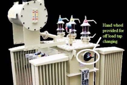
Transformer cooling media faults, Transformer tap changing faults are considered as mechanical faults. The cooling medium failure results in high temperatures in transformer which effects the insulation and casing. In long run this may result deterioration of component or even it may also create fire in the transformer. In transformer tap changing mechanism there will be high current flow in the taping, if any fault in this mechanism may result in flashing at tap changers. In OLTC this problem is very high compared to offload tap changer.

Through Faults:

These are the faults which occurs outside the transformer zone and cleared by the down stream components. However the fault is not cleared by them, it may results in severe over loading on transformer which results in large current flow through the transformer. If the fault is at secondary side then a large current flow will result in secondary and it reflects high current flow in corresponding primary winding. These faults are not serious but these may deteriorate the insulation of the transformer and may create long time fault.  Normally these faults are cleared by over current protection which is placed on transformer primary.

Typical protections in transformer

Typically transformer protections are classified as two types.  1) Main protections 2) backup protections.

Main protections: These are immediate fault clearance protections which acts instantaneously to clear the faults in the transformer.

  • Differential protection (87 T)
  • Over current protection (51)

Back up protection: These protections will acts as a back up to the main protections i.e. if the main protection fails corresponding back up protection will act and safe guard the device from fault.

  • Over voltage
  • Volts/hertz
  • Negative phase sequence relay
Don't Miss Our Updates
Be the first to get exclusive content straight to your email.
We promise not to spam you. You can unsubscribe at any time.
Invalid email address
You've successfully subscribed !

Continue Reading

Transformer Tap Changing Working Principle
Induction Motors Faults and Protection
Losses in a DC Generator
BLDC Motor Vs AC Induction Motor
Synchronous Motor Is Not Self Starting?
Synchronous Motor Working Principle
Share This Article
Facebook Whatsapp Whatsapp LinkedIn Copy Link
Share
Leave a Comment

Leave a Reply Cancel reply

Your email address will not be published. Required fields are marked *

Stay Connected

128.3kFollowersLike
69.1kFollowersFollow
210kSubscribersSubscribe
38kFollowersFollow

Categories

Explore More

What is a transformer tap changer?
Use of line reactors
How Motor Star Delta Starter Works ?
Basics of AC Induction Motors
Induction Motor Operating Characteristics
What happen When Synchronous Generator loss Excitation
Advantages & Disadvantages of Synchronous Motors
Difference Between Squirrel Cage and Slip Ring Motors

Keep Learning

DC motor speed control

DC Motor Speed Control

Metering pumps

Metering Pumps

Synchronous Generator Salient Pole vs Non Salient Pole

Advantages and Disadvantages of Squirrel Cage Induction motor

Transformer Open and Short Circuit Tests

Squirrel Cage Induction Motor vs Slip Ring Induction Motor

Electrical-Switches-Working-Animation

Difference between Star and Delta Connections

Electrical Machines Objective Questions

Electrical Machines Objective Questions

Learn More

Open Tank DP Level Measurement

Open Tank DP Level Transmitter Calculations

Ultrasonic Flowmeters Principle

Factors Affecting the Performance of Ultrasonic Flow Meters

Smart DP transmitter Formula

DP Transmitter Error Calculations

Comparison of Absorption Chillers and Electric (Compression) Chillers

Difference between HVAC Absorption Chillers and Electric Chillers

How to Test a Transistor

How to Test a Transistor ?

PLC Program to Control Level of Two Tanks

PLC Level Control of Two Tanks

How are Silicon Chips Disposed?

How are Silicon Chips Disposed?

Omron PLC Instructions - Move, Move Bit, Move Digit

Move, Move Bit, Move Digit – Examples of Omron PLC Programs

Menu

  • About
  • Privacy Policy
  • Copyright

Quick Links

  • Learn PLC
  • Helping Hand
  • Part Time Job

YouTube Subscribe

Follow US
All rights reserved. Reproduction in whole or in part without written permission is prohibited.
Welcome Back!

Sign in to your account

Username or Email Address
Password

Lost your password?