Inst ToolsInst ToolsInst Tools
  • Courses
  • Automation
    • PLC
    • Control System
    • Safety System
    • Communication
    • Fire & Gas System
  • Instrumentation
    • Design
    • Pressure
    • Temperature
    • Flow
    • Level
    • Vibration
    • Analyzer
    • Control Valve
    • Switch
    • Calibration
    • Erection & Commissioning
  • Interview
    • Instrumentation
    • Electrical
    • Electronics
    • Practical
  • Q&A
    • Instrumentation
    • Control System
    • Electrical
    • Electronics
    • Analog Electronics
    • Digital Electronics
    • Power Electronics
    • Microprocessor
  • Request
Search
  • Books
  • Software
  • Projects
  • Process
  • Tools
  • Basics
  • Formula
  • Power Plant
  • Root Cause Analysis
  • Electrical Basics
  • Animation
  • Standards
  • 4-20 mA Course
  • Siemens PLC Course
Reading: Current Limiting Reactors and Short Circuit Currents
Share
Font ResizerAa
Inst ToolsInst Tools
Font ResizerAa
  • Courses
  • Design
  • PLC
  • Interview
  • Control System
Search
  • Courses
  • Automation
    • PLC
    • Control System
    • Safety System
    • Communication
    • Fire & Gas System
  • Instrumentation
    • Design
    • Pressure
    • Temperature
    • Flow
    • Level
    • Vibration
    • Analyzer
    • Control Valve
    • Switch
    • Calibration
    • Erection & Commissioning
  • Interview
    • Instrumentation
    • Electrical
    • Electronics
    • Practical
  • Q&A
    • Instrumentation
    • Control System
    • Electrical
    • Electronics
    • Analog Electronics
    • Digital Electronics
    • Power Electronics
    • Microprocessor
  • Request
Follow US
All rights reserved. Reproduction in whole or in part without written permission is prohibited.
Inst Tools > Blog > Power Systems > Current Limiting Reactors and Short Circuit Currents

Current Limiting Reactors and Short Circuit Currents

Last updated: September 20, 2016 2:15 pm
Editorial Staff
Power Systems
No Comments
Share
3 Min Read
SHARE

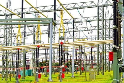
A current limiting reactors is also called as series reactors. It is an inductive coil having large inductive reactance compared to the resistance and is used to limit the short circuit current during fault conditions. These reactors are connected in feeders and ties, in generator leads and between the bus sections to reduce the magnitude of the short circuit current. The reactor allow free interchange of power under normal condition. however during fault condition the disturbance is confined to only faulty location.As the resistance of the reactors are small compared to reactance the efficiency of the system is not affected much

Short circuit current is reduced by an increase in the reactance of the system. Short circuit current depends on the generating capacity, voltage at the fault point and the total reactance between the generating point and the fault location. Breaking capacity of the circuit breaker depends on the magnitude of the fault current. If the fault current is beyond the designed limit of the breaking capacity of the breaker, the fault cannot be extinguish. Therefore in large interconnected power system large number of generators and motors feed the fault on occurrence of the fault. Therefore at times the magnitude of the short circuit current exceeds the breaking capacity of the breaker. Therefore it is necessary to limit the fault current by some means. By including a reactor or few reactors at some strategic locations, short circuit currents at different points can be reduced.

Advantages:

  • Protective reactors are used to reduce the flow of short circuit current at the fault point so as to protect the apparatus from excessive mechanical stresses and from over heating and thus protect the system as a whole
  • Protective systems are used to reduce the voltage disturbances caused by the short circuits
  • They also localize the fault by limiting the current that flow in to the fault from other healthy feeders or parts of the system thereby avoiding the fault by spreading
  • It helps to reduce the duty imposed on the switching equipment during fault conditions

Disadvantages:

  • Total percentage reactance of the system increases thereby causing increase in reactive voltage drop and decrease in power factor due to increased angle of lag. Thus regulation of the system becomes poor.
Don't Miss Our Updates
Be the first to get exclusive content straight to your email.
We promise not to spam you. You can unsubscribe at any time.
Invalid email address
You've successfully subscribed !

Continue Reading

Why Symmetrical Components Used for Unbalanced faults in Power System
Neutral Grounding Practice in Power System
Voltage Variations Effects on Power Plant Equipment
Harmonics effect on Transformer
Ungrounded or Isolated Neutral System Disadvantages
Rotor Angle Stability of Synchronous Generators in Power System
Share This Article
Facebook Whatsapp Whatsapp LinkedIn Copy Link
Share
Leave a Comment

Leave a Reply Cancel reply

Your email address will not be published. Required fields are marked *

Stay Connected

128.3kFollowersLike
69.1kFollowersFollow
210kSubscribersSubscribe
38kFollowersFollow

Categories

Explore More

Electrical Power System Protection Quiz
Factors affect Voltage Level Selection in Service System
Silicon Carbide Lightning Arresters Working Principle
Why Reactive Power is Generated at Load
Shunt Capacitor Advantages in Power System
Harmonics effect on Induction Motor
Underground Cable Fault Identification Methods
Reactive Power Sources and Sinks in Power System

Keep Learning

harmonics-disadvantages-in-power-system

Harmonics Disadvantages in Power System

Power System Protection Multiple Choice Questions

Power System Protection Multiple Choice Questions

Advantages & Disadvantages of AC power and DC power

Advantages & Disadvantages of AC power and DC power

Auto Recloser Circuit Breaker in Power System

Auto Recloser Circuit Breaker in Power System

Corona-Ring-on-Surge-Arresters

Corona Ring on Surge Arresters and other EHV equipment

Advantages and Disadvantages of Network Topology

Advantages and Disadvantages of Per Unit System

Shunt Vs Series Capacitors Advantages

Shunt Vs Series Capacitors Advantages

Transformer Tap changer

Ferroresonance in Power Transformers

Learn More

Hydrazine analyzer Working Principle

Hydrazine Analyzer Working Principle

Types of Industrial Storage Batteries

Types of Industrial Storage Batteries

liquid flow control system

Practical Process Control System Questions & Answers – 7

Industrial Star Delta Starter for 3-Phase Induction Motor

Star Delta Starter – Working, Circuit, Advantages, Disadvantages

open vs closed loop

Open Loop and Closed Loop Animation

Controller Output Current Loop

DCS Controllers to Output Current Loops

foundation-fieldbus-vs-profibus

Comparison between Foundation Fieldbus and Profibus

PLC Tag Naming Conventions

PLC Tag Naming Conventions

Menu

  • About
  • Privacy Policy
  • Copyright

Quick Links

  • Learn PLC
  • Helping Hand
  • Part Time Job

YouTube Subscribe

Follow US
All rights reserved. Reproduction in whole or in part without written permission is prohibited.
Welcome Back!

Sign in to your account

Username or Email Address
Password

Lost your password?