Inst ToolsInst ToolsInst Tools
  • Courses
  • Automation
    • PLC
    • Control System
    • Safety System
    • Communication
    • Fire & Gas System
  • Instrumentation
    • Design
    • Pressure
    • Temperature
    • Flow
    • Level
    • Vibration
    • Analyzer
    • Control Valve
    • Switch
    • Calibration
    • Erection & Commissioning
  • Interview
    • Instrumentation
    • Electrical
    • Electronics
    • Practical
  • Q&A
    • Instrumentation
    • Control System
    • Electrical
    • Electronics
    • Analog Electronics
    • Digital Electronics
    • Power Electronics
    • Microprocessor
  • Request
Search
  • Books
  • Software
  • Projects
  • Process
  • Tools
  • Basics
  • Formula
  • Power Plant
  • Root Cause Analysis
  • Electrical Basics
  • Animation
  • Standards
  • 4-20 mA Course
  • Siemens PLC Course
Reading: DC Circuits Multiple Choice Questions
Share
Font ResizerAa
Inst ToolsInst Tools
Font ResizerAa
  • Courses
  • Design
  • PLC
  • Interview
  • Control System
Search
  • Courses
  • Automation
    • PLC
    • Control System
    • Safety System
    • Communication
    • Fire & Gas System
  • Instrumentation
    • Design
    • Pressure
    • Temperature
    • Flow
    • Level
    • Vibration
    • Analyzer
    • Control Valve
    • Switch
    • Calibration
    • Erection & Commissioning
  • Interview
    • Instrumentation
    • Electrical
    • Electronics
    • Practical
  • Q&A
    • Instrumentation
    • Control System
    • Electrical
    • Electronics
    • Analog Electronics
    • Digital Electronics
    • Power Electronics
    • Microprocessor
  • Request
Follow US
All rights reserved. Reproduction in whole or in part without written permission is prohibited.
Inst Tools > Blog > Multiple Choice Questions > DC Circuits Multiple Choice Questions

DC Circuits Multiple Choice Questions

Last updated: November 3, 2017 4:21 am
Editorial Staff
Multiple Choice Questions
No Comments
Share
3 Min Read
SHARE

DC Circuits Multiple Choice Questions

Question 1

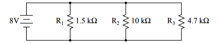
Determine the voltage dropped across resistor R3 in this circuit:
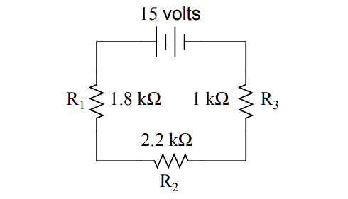
DC Circuit

(A) 7.5 volts
(B) 3.0 volts
(C) 6.6 volts
(D) 15 volts
(E) 5.4 volts

Answer : B

Question 2

Calculate total current in this circuit:

DC circuit theory

(A) 8.000 mA
(B) 7.835 mA
(C) 8.168 mA
(D) 493.8 µA
(E) 5.333 mA

Answer : B

Question 3

Calculate the necessary resistor value (R) to balance this bridge circuit:
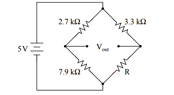
bridge circuit

(A) 7.299 kΩ
(B) 6.464 kΩ
(C) 9.656 kΩ
(D) 8.501 kΩ
(E) 5.830 kΩ

Answer : C

Question 4

Calculate the necessary resistor size for R1 to make the total circuit current equal to 30 milliamps:
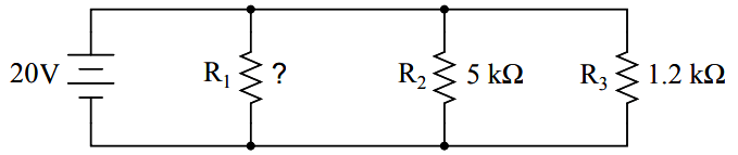
Calculate Circuit Resistance

(A) 2.143 kΩ
(B) 1.500 kΩ
(C) 967.7 Ω
(D) 666.7 Ω
(E) 310.0 Ω

Answer : A

Question 5

Calculate the current through resistor R4 in this circuit:
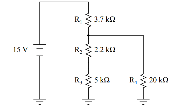
Calculate Circuit Current

(A) 1.226 mA
(B) 441.5 µA
(C) 1.668 mA
(D) 4.054 mA
(E) 8.994 mA

Answer : B

Question 6

Voltages and currents in an RC or LR time-constant circuit will settle to within 1% of their final value(s) in how many time constants?

(A) 10
(B) 3
(C) 5
(D) 2
(E) 4

Answer : C

Question 7

How much voltage will a DMM register if connected with the red test lead on point B and the black test lead on point D?
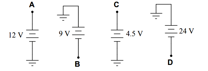
Battery Voltage

(A) +15 volts
(B) -33 volts
(C) +33 volts
(D) -9 volts
(E) -15 volts

Answer : A

Question 8

Calculate the voltage between test point B and ground in this circuit:
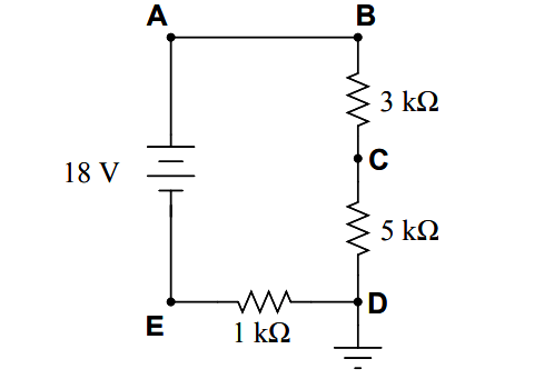
Calculate the voltage between test point

(A) 20 volts
(B) 18 volts
(C) 2 volts
(D) 6 volts
(E) 16 volts

Answer : E

Question 9

Determine the magnitude and direction of current through resistor R4 in this circuit:

circuit electron flow

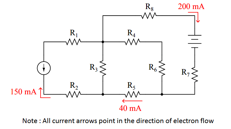
(A) 240 mA → (left to right)
(B) 160 mA ← (right to left)
(C) 200 mA → (left to right)
(D) 240 mA ← (right to left)
(E) 160 mA → (left to right)

Answer : B

Question 10

Determine the magnitude and polarity of the voltage across resistor R4 in this circuit:

Determine the magnitude and polarity of the voltage

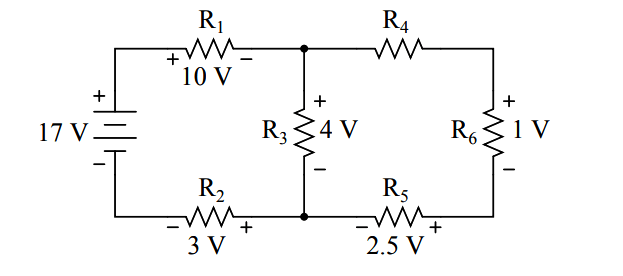
(A) – 1.0 volt + (negative on left, positive on right)
(B) – 7.0 volts + (negative on left, positive on right)
(C) + 0.5 volts – (positive on left, negative on right)
(D) – 3.5 volts + (negative on left, positive on right)
(E) + 4.0 volts – (positive on left, negative on right)

Answer : C

Credits : by Tony R. Kuphaldt

Don't Miss Our Updates
Be the first to get exclusive content straight to your email.
We promise not to spam you. You can unsubscribe at any time.
Invalid email address
You've successfully subscribed !

Continue Reading

Mathematical Preliminaries
Optimal Control Problems – Part 2
Z-transform Analysis of Sampled-Data Control Systems
Feedback Control Loop Questions & Answers
Instrumentation of ESR Spectrometer
Hydraulic Systems Objective Questions
Share This Article
Facebook Whatsapp Whatsapp LinkedIn Copy Link
Share
Leave a Comment

Leave a Reply Cancel reply

Your email address will not be published. Required fields are marked *

Stay Connected

128.3kFollowersLike
69.1kFollowersFollow
210kSubscribersSubscribe
38kFollowersFollow

Categories

Explore More

Bode Plots MCQ
Parameter Optimization
Construction of Phase -Trajectories
Ion Spectroscopy Questions & Answers
X-Ray Spectroscopy Questions & Answers
AC Circuits Multiple Choice Questions
Ionization of Gases Questions and Answers
Magnetic Deflection Mass Spectrometer Questions & Answers

Keep Learning

Optimal Control Systems

The Infinite Time Regulator Problem

Feedforward Control Questions & Answers

Feedforward Control Questions and Answers

Analyzers Questions and Answers

Electrochemical Methods for Oxygen Analysis Questions & Answers

Chromatography Questions & Answers

Gas Solid Chromatography Questions & Answers

Analyzers Questions and Answers

Electron Probe Microanalyser Questions & Answers

Feedback Characteristics of Control Systems

Controller Components – Part 2 Objective Questions

Electron Spin Resonance Questions & Answers

Electron Spin Resonance

Stability in Frequency Domain

Tuning of PID Controllers

Learn More

Temperature Transmitter Formula

Calculate Temperature Transmitter Output

Conveyor Control with Main Motor and Backup Motor

Conveyor Operation with a Backup Motor using PLC Ladder Diagram

Digital Electronics Multiple Choice Questions

Erasable Programmable Read Only Memory Objective Questions

Electromagnetic Fields Objective Questions

Electromagnetic Fields Objective Questions

Example PLC Program to Control a Pump based on Level Sensors

Example PLC Program to Control a Pump based on Level Sensors

User Defined Data Types - UDT

User Defined Data Types (UDT) – Purpose, Need, Tutorial

What is Pump Redundancy

What is Pump Redundancy?

Intrinsic Safety of Instruments

Intrinsic Safety of Instruments

Menu

  • About
  • Privacy Policy
  • Copyright

Quick Links

  • Learn PLC
  • Helping Hand
  • Part Time Job

YouTube Subscribe

Follow US
All rights reserved. Reproduction in whole or in part without written permission is prohibited.
Welcome Back!

Sign in to your account

Username or Email Address
Password

Lost your password?