Inst ToolsInst ToolsInst Tools
  • Courses
  • Automation
    • PLC
    • Control System
    • Safety System
    • Communication
    • Fire & Gas System
  • Instrumentation
    • Design
    • Pressure
    • Temperature
    • Flow
    • Level
    • Vibration
    • Analyzer
    • Control Valve
    • Switch
    • Calibration
    • Erection & Commissioning
  • Interview
    • Instrumentation
    • Electrical
    • Electronics
    • Practical
  • Q&A
    • Instrumentation
    • Control System
    • Electrical
    • Electronics
    • Analog Electronics
    • Digital Electronics
    • Power Electronics
    • Microprocessor
  • Request
Search
  • Books
  • Software
  • Projects
  • Process
  • Tools
  • Basics
  • Formula
  • Power Plant
  • Root Cause Analysis
  • Electrical Basics
  • Animation
  • Standards
  • 4-20 mA Course
  • Siemens PLC Course
Reading: Importance of Hysteresis Loop
Share
Font ResizerAa
Inst ToolsInst Tools
Font ResizerAa
  • Courses
  • Design
  • PLC
  • Interview
  • Control System
Search
  • Courses
  • Automation
    • PLC
    • Control System
    • Safety System
    • Communication
    • Fire & Gas System
  • Instrumentation
    • Design
    • Pressure
    • Temperature
    • Flow
    • Level
    • Vibration
    • Analyzer
    • Control Valve
    • Switch
    • Calibration
    • Erection & Commissioning
  • Interview
    • Instrumentation
    • Electrical
    • Electronics
    • Practical
  • Q&A
    • Instrumentation
    • Control System
    • Electrical
    • Electronics
    • Analog Electronics
    • Digital Electronics
    • Power Electronics
    • Microprocessor
  • Request
Follow US
All rights reserved. Reproduction in whole or in part without written permission is prohibited.
Inst Tools > Blog > Electrical Machines > Importance of Hysteresis Loop

Importance of Hysteresis Loop

Last updated: December 22, 2018 1:16 am
Editorial Staff
Electrical Machines
1 Comment
Share
5 Min Read
SHARE

Hysteresis Loss:

When a magnetic material is subjected to a cycle of magnetization (magnetized first in one direction and later magnetized in opposite direction in a cyclic manner), an energy loss takes place. This energy loss is due to molecular friction in the material. That is, the domains (or molecular magnets) of the material being turned first in one direction and then the other. Energy is thus expended in the material in overcoming this opposition. This loss is in the form of heat and is called hysteresis loss.

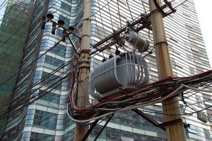
Hysteresis loss is present in all electrical machines whose iron parts are subjected to cycle of magnetization like transformers, induction motors and other machines operated on ac supply. When an alternating supply is provided to the electrical machines the flux in the iron of these machines change in both direction and value alternatively. During this process energy is lost and this loss constitutes the core loss of the machine. The obvious effect of hysteresis loss is the rise of temperature of the machine

  • Transformers and most electric machines operate on alternating current. In such devices, the flux in the iron changes continuously, both in magnitude and in direction. Hence hysteresis loss occurs in these machines
  • Hysteresis loss also occurs when iron parts rotates in constant magnetic field eg- dc machines

Hysteresis Loop or B-H Loop area:

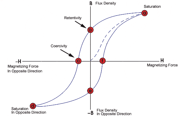
Hysteresis loop is obtained by plotting B-H (B: flux density, H:magnetizing force) of iron for one cycle of magnetization.
Hysteresis Loss

When the core of the machine such as transformer, induction motors is magnetized with the magnetizing force (H) by applying voltage, magnetic flux density (B) increases as shown in the figure (dotted lines) and saturates (first quadrant). Saturation region in one in which increase in the magnetization force (H) will not further appreciably increase the magnetic flux density (B) in the material.

When the applied voltage reaches back to the zero position from the peak (first half cycle), magnetizing force will also becomes zero. However the magnetic flux density in the core will not reach zero but have some finite value. This property of magnetic material to withhold some flux (B) when magnetizing strength becomes zero is called Retentivity.

During the next half cycle all the domains in the magnetic core tries to align in opposite direction as the applied voltage polarity changes and hence the magnetizing force applied. With increase in the magnetizing force (H) a point is reached where the magnetic flux density(B) becomes zero. This point is called coercivity. Beyond this point, magnetic flux will be in opposite direction with increase in field strength and reaches saturation as shown in figure (third quadrant).

Further applied magnetic field will starts decreasing from peak and reaches zero. This decrease in the magnetic flux with decrease in field strength can be seen in figure (third quadrant) and reaches back when the voltage polarity changes.

This forms the B-H loop of hysteresis loop of the magnetic material of the machines

Importance or Significance of B-H Loop:

The shape and size of the hysteresis loop largely depends on the nature of the magnetic material. The choice of a magnetic material required for a particular application often depends on the shape and size of the hysteresis loop.

  • The smaller the hysteresis loop area of a magnetic material, the less is the hysteresis loss. For example, the hysteresis loop area for silicon steel has very small, for this reason silicon steel is widely used for manufacturing of transformer cores and rotating machines which are subjected to rapid reversals of magnetism
  • The hysteresis loop for Hard Steel (large hysteresis loop area) indicates that the material has high retentivity and coercivity. Therefore hard steel is quite useful in making permanent magnets. But due to large area hysteresis loss is quite high. This is the reason hard steel is not used for construction of electrical machines

Methods to reduce Hysteresis Loop or B-H Loop:

Hysteresis loop can by using soft magnetic materials (like CRGO core magnetic material in transformers) having smaller loop to reduce the hysteresis loss.
Don't Miss Our Updates
Be the first to get exclusive content straight to your email.
We promise not to spam you. You can unsubscribe at any time.
Invalid email address
You've successfully subscribed !

Continue Reading

Applications of Synchronous Motors
Different Types of Transformers
How Motor Star Delta Starter Works ?
AC Motor Braking
Advantages & Disadvantages of Variable Speed Drives
Difference between Induction motor and Synchronous motor
Share This Article
Facebook Whatsapp Whatsapp LinkedIn Copy Link
Share
1 Comment
  • Manikanta Prasad says:
    April 6, 2018 at 8:21 am

    This app gives us more knowledge.

    Reply

Leave a Reply Cancel reply

Your email address will not be published. Required fields are marked *

Stay Connected

128.3kFollowersLike
69.1kFollowersFollow
210kSubscribersSubscribe
38kFollowersFollow

Categories

Explore More

What is a Transformer Tap Changer
Metering Pumps
Transformer Open and Short Circuit Tests
Parallel Operation of Alternators
Synchronous Motor Is Not Self Starting?
Synchronous Motor Starting Methods
DC Motor Applications in Industries
Types of AC Motors and DC Motors

Keep Learning

Off load Tap Changer Principle

Transformer Tap Changing Working Principle

Why Armature is placed on Stator for Synchronous machines

AC Induction Motor Construction

Basics of AC Induction Motors

BLDC Motor Vs AC Induction Motor

Faults in a Transformer

Losses of Transformer

Types of Transfomer Cooling Methods

Synchronous Generator Salient Pole vs Non Salient Pole

Learn More

Difference between Compact PLC and Modular PLC

Difference between Compact PLC and Modular PLC

Difference Between Adhesion and Cohesion

Difference Between Adhesion and Cohesion

Smart DP transmitter Formula

Smart DP Transmitter Flow Meter Calculations

Modbus

Modbus : History, Structure, Modes, Addressing, Functions

ON OFF Valve Parts

ON OFF Valve Preventive Maintenance and Testing Procedure

Pressure Measurement using Manometer

Pressure Measurement using Manometer

pH Analyzer Do’s and Don’ts

pH Analyzer Do’s and Don’ts

Averaging Pitot Tube Working Principle

Pitot Tube Working Principle

Menu

  • About
  • Privacy Policy
  • Copyright

Quick Links

  • Learn PLC
  • Helping Hand
  • Part Time Job

YouTube Subscribe

Follow US
All rights reserved. Reproduction in whole or in part without written permission is prohibited.
Welcome Back!

Sign in to your account

Username or Email Address
Password

Lost your password?