Inst ToolsInst ToolsInst Tools
  • Courses
  • Automation
    • PLC
    • Control System
    • Safety System
    • Communication
    • Fire & Gas System
  • Instrumentation
    • Design
    • Pressure
    • Temperature
    • Flow
    • Level
    • Vibration
    • Analyzer
    • Control Valve
    • Switch
    • Calibration
    • Erection & Commissioning
  • Interview
    • Instrumentation
    • Electrical
    • Electronics
    • Practical
  • Q&A
    • Instrumentation
    • Control System
    • Electrical
    • Electronics
    • Analog Electronics
    • Digital Electronics
    • Power Electronics
    • Microprocessor
  • Request
Search
  • Books
  • Software
  • Projects
  • Process
  • Tools
  • Basics
  • Formula
  • Power Plant
  • Root Cause Analysis
  • Electrical Basics
  • Animation
  • Standards
  • 4-20 mA Course
  • Siemens PLC Course
Reading: Surge Impedance Loading of Transmission Line
Share
Font ResizerAa
Inst ToolsInst Tools
Font ResizerAa
  • Courses
  • Design
  • PLC
  • Interview
  • Control System
Search
  • Courses
  • Automation
    • PLC
    • Control System
    • Safety System
    • Communication
    • Fire & Gas System
  • Instrumentation
    • Design
    • Pressure
    • Temperature
    • Flow
    • Level
    • Vibration
    • Analyzer
    • Control Valve
    • Switch
    • Calibration
    • Erection & Commissioning
  • Interview
    • Instrumentation
    • Electrical
    • Electronics
    • Practical
  • Q&A
    • Instrumentation
    • Control System
    • Electrical
    • Electronics
    • Analog Electronics
    • Digital Electronics
    • Power Electronics
    • Microprocessor
  • Request
Follow US
All rights reserved. Reproduction in whole or in part without written permission is prohibited.
Inst Tools > Blog > Transmission & Distribution > Surge Impedance Loading of Transmission Line

Surge Impedance Loading of Transmission Line

Last updated: September 19, 2016 2:27 am
Editorial Staff
Transmission & Distribution
No Comments
Share
3 Min Read
SHARE

Loading of any transmission line depends on,

  • Thermal limitation (I2R limitation)
  • Voltage regulation
  • Stability Limitation

This is defined as the load (of unity power factor) that can be delivered by the line of negligible resistance.

surge-impedance-loading-of-transmission-line

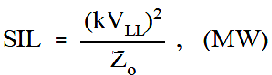
Where VLL is the receiving end voltage in kV and Zo is the surge impedance in ohms, and SIL is the surge impedance loading or natural loading of the line

The above  expression gives a limit of the maximum power that can be delivered by a line and is useful in designing the transmission line. This can be used for the comparison of loads that can be carried on the transmission lines at different voltages

From the above expression power transmitted through a long transmission lines can be either increased by increasing the value of the receiving end line voltage (VLL) or by reducing the surge impedance (Zo). Voltage transmission capability is increased day by day, this is the most commonly adopted method for increasing the power limit of the heavily loaded transmission line. But there is a limit beyond which is neither economical nor practical to increase the receiving end line voltage

By applying some methods such as introducing series capacitors (capacitors in series with the transmission line) or shunt capacitors (capacitors in parallel with transmission lines) can be used to reduce the value of surge impedance (Zo).

Surge Impedance Loading

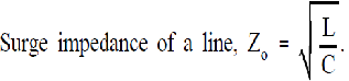
Surge Impedance Loading (SIL) can be increased by reducing the Surge impedance of the line. From the above expression Zo can be decreased by either increasing the capacitance (C) of the line or by reducing the inductance (L) of the line. Inductance (L) of the transmission line cannot be reduced easily

By use of the series capacitors surge impedance (Zo) and the phase shift get reduced due to decrease in the line inductance (L). This improves the system stability limit. These capacitors also helps in reducing the line drops and so voltage variations. But this method causes difficulty under short circuit conditions of system as capacitors will get damage.

By use of shunt capacitors though the surge impedance (Zo) is reduced but the phase shift of the system increases this affects the poor stability in the system specially when synchronous machines are under the load. This method is not employed in long transmission lines specially when stability limits are present

Don't Miss Our Updates
Be the first to get exclusive content straight to your email.
We promise not to spam you. You can unsubscribe at any time.
Invalid email address
You've successfully subscribed !

Continue Reading

Advantages & Disadvantages of AC and DC Power Transmission
Single Phase Earth Return System Advantages & Disadvantages
Classification of Transmission Lines
Charging Currents in Transmission Lines
Difference between Solid Conductor and Stranded Conductor
Advantages of Bundled Conductors in Transmission Lines
Share This Article
Facebook Whatsapp Whatsapp LinkedIn Copy Link
Share
Leave a Comment

Leave a Reply Cancel reply

Your email address will not be published. Required fields are marked *

Stay Connected

128.3kFollowersLike
69.1kFollowersFollow
210kSubscribersSubscribe
38kFollowersFollow

Categories

Explore More

Electrical Power Transmission And Distribution
Insulating Material for Cable Requirements
Conductor Size Selection in Distribution Power System
Advantages of Suspension Insulators and Pin type Insulators
Advantages of HVDC transmission
Voltage Control Methods at Distribution System
Current Limiting Reactors in Power System
Comparison of HVDC transmission and HVAC transmission

Keep Learning

Electrical Power Distribution

Electrical Power Distribution

Learn More

What is Static Grounding

What is Static Grounding?

factorytalk view studio hmi

How to Create Templates in FactoryTalk View Studio?

Alarms to Annunciator

Basics of Alarms and Trips

Create PLC Program based on Logic Circuit

Create PLC Program based on Logic Circuit

Allen-Bradley MicroLogix controller

Programmable Logic Controller (PLC) Questions and Answers – 16

Measurement and Instrumentation Objective Questions

Measurements & Instrumentation Quiz – Set 1

Differences between No-load Supply Current and Load Current

Differences between No-load Supply Current and Load Current

Orifice Flow Measurement Formula

Basics of Flow Measurement

Menu

  • About
  • Privacy Policy
  • Copyright

Quick Links

  • Learn PLC
  • Helping Hand
  • Part Time Job

YouTube Subscribe

Follow US
All rights reserved. Reproduction in whole or in part without written permission is prohibited.
Welcome Back!

Sign in to your account

Username or Email Address
Password

Lost your password?