Inst ToolsInst ToolsInst Tools
  • Courses
  • Automation
    • PLC
    • Control System
    • Safety System
    • Communication
    • Fire & Gas System
  • Instrumentation
    • Design
    • Pressure
    • Temperature
    • Flow
    • Level
    • Vibration
    • Analyzer
    • Control Valve
    • Switch
    • Calibration
    • Erection & Commissioning
  • Interview
    • Instrumentation
    • Electrical
    • Electronics
    • Practical
  • Q&A
    • Instrumentation
    • Control System
    • Electrical
    • Electronics
    • Analog Electronics
    • Digital Electronics
    • Power Electronics
    • Microprocessor
  • Request
Search
  • Books
  • Software
  • Projects
  • Process
  • Tools
  • Basics
  • Formula
  • Power Plant
  • Root Cause Analysis
  • Electrical Basics
  • Animation
  • Standards
  • 4-20 mA Course
  • Siemens PLC Course
Reading: Shunt Vs Series Capacitors Advantages
Share
Font ResizerAa
Inst ToolsInst Tools
Font ResizerAa
  • Courses
  • Design
  • PLC
  • Interview
  • Control System
Search
  • Courses
  • Automation
    • PLC
    • Control System
    • Safety System
    • Communication
    • Fire & Gas System
  • Instrumentation
    • Design
    • Pressure
    • Temperature
    • Flow
    • Level
    • Vibration
    • Analyzer
    • Control Valve
    • Switch
    • Calibration
    • Erection & Commissioning
  • Interview
    • Instrumentation
    • Electrical
    • Electronics
    • Practical
  • Q&A
    • Instrumentation
    • Control System
    • Electrical
    • Electronics
    • Analog Electronics
    • Digital Electronics
    • Power Electronics
    • Microprocessor
  • Request
Follow US
All rights reserved. Reproduction in whole or in part without written permission is prohibited.
Inst Tools > Blog > Power Systems > Shunt Vs Series Capacitors Advantages

Shunt Vs Series Capacitors Advantages

Last updated: September 21, 2016 10:39 am
Editorial Staff
Power Systems
1 Comment
Share
2 Min Read
SHARE

Shunt Vs Series Capacitors Advantages

Capacitors aid in minimizing losses and helps in reducing operating expenses. Capacitors should be placed where the reactive power demand is more as capacitors generate reactive power and helps to maintain the voltage. Basically reactive power demand will be more at load side of the power system, hence capacitors should be placed as close as possible to load. In specific, capacitor banks should be placed where the low voltage problem occurs.Shunt capacitors are series capacitors are employed in power system for different purposes

  • Shunt capacitors and series capacitors in the power system generate the reactive power to improve the power factor and voltage, thereby enhancing the power system capacity and reducing the losses. In series capacitors reactive power generation is proportional to the square of the load current (I2Xc), whereas in shunt capacitors reactive power generation is proportional to the square of the voltage (V2/Xc).
  • The cost of installation of series capacitors is higher than that of the shunt capacitors. This is because the protective equipment for the series capacitors is often complicated. In addition to that, series capacitors are generally designed for higher power to cope up with the future increase in the load
  • For the same voltage improvement, the rating of the shunt capacitors will be higher than that of series capacitors. Series capacitors compensation may create certain disturbances: ferro-resonance in transformers, sub-synchronous resonance during motor starting, shunting of motors during normal operation and difficulty in protection of capacitors from system faults.
  • Series capacitors are more effective on distribution circuits with higher X/R ratio and for load variations involving a higher reactive content.
  • Series capacitors are generally employed to improve the stability of the system and shunt capacitors are generally employed to improve the power factor of the system

Some of the factors which influence the choice between the shunt and series capacitors are tabulated below:

Shunt Vs Series Capacitors Advantages

Don't Miss Our Updates
Be the first to get exclusive content straight to your email.
We promise not to spam you. You can unsubscribe at any time.
Invalid email address
You've successfully subscribed !

Continue Reading

Rotor Angle Stability of Synchronous Generators in Power System
Why Symmetrical Components Used for Unbalanced faults in Power System
Silicon Carbide Lightning Arresters Working Principle
Factors affect Voltage Level Selection in Service System
Harmonics effect on Transformer
Ferroresonance in Power Transformers
Share This Article
Facebook Whatsapp Whatsapp LinkedIn Copy Link
Share
1 Comment
  • F Dormani says:
    February 22, 2022 at 11:20 am

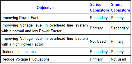
    1. The first “are” shall be “and” on your essay “Shunt capacitors are series capacitors are”
    2. The above table is confusing. Are you talking about transformer, lines , etc.?

    Reply

Leave a Reply Cancel reply

Your email address will not be published. Required fields are marked *

Stay Connected

128.3kFollowersLike
69.1kFollowersFollow
210kSubscribersSubscribe
38kFollowersFollow

Categories

Explore More

Electrical Power System Protection Quiz
Harmonics Disadvantages in Power System
Power System Protection Multiple Choice Questions
Auto Recloser Circuit Breaker in Power System
Advantages & Disadvantages of AC power and DC power
Underground Cable Fault Identification Methods
Ungrounded or Isolated Neutral System Disadvantages
Why Reactive Power is Generated at Load

Keep Learning

Why Grounding

Generating Station Grounding Principles

Advantages and Disadvantages of Network Topology

Advantages and Disadvantages of Per Unit System

Reactive Power Sources and Sinks in Power System

Reactive Power Sources and Sinks in Power System

Corona-Ring-on-Surge-Arresters

Corona Ring on Surge Arresters and other EHV equipment

shunt-capacitor-advantages-in-power-system

Shunt Capacitor Advantages in Power System

harmonics-effect-on-induction-motor

Harmonics effect on Induction Motor

neutral-grounding-practice-in-power-system

Neutral Grounding Practice in Power System

current-limiting-reactors-and-short-circuit-currents

Current Limiting Reactors and Short Circuit Currents

Learn More

fire alarm system operation

What is Fire Alarm System?

Level Loop Troubleshooting

Identify Faults in PID Control Loop

Save and BR Memory in Siemens PLC Programming

SAVE and BR Memory Instructions in Siemens PLC Programming

Pressure Manometer

Types of Manometers

Radio Telemetry Objective Questions

Radio Telemetry Objective Questions

Field Instruments

#11 PLC Best Practices – Instrument for Plausibility Checks

Impulse line - Purpose & Tapping Point Location

Impulse Line – Purpose & Tapping Point Location

Cable Glands

Using of MCT instead of Cable Glands on the Cabinets

Menu

  • About
  • Privacy Policy
  • Copyright

Quick Links

  • Learn PLC
  • Helping Hand
  • Part Time Job

YouTube Subscribe

Follow US
All rights reserved. Reproduction in whole or in part without written permission is prohibited.
Welcome Back!

Sign in to your account

Username or Email Address
Password

Lost your password?