Here we shall see recommended practices for the protection of the instrument from harsh process conditions. In this article, we shall learn about the purging methods to protect the instrument.
Purging of Instruments
Although purges are difficult to maintain, some process measurements are made possible only by the use of purging.
Purge fluids are introduced into the instrument impulse lines, manifold valves, or the instrument itself and flow out through the process connections.
The purge fluid serves to seal the instrument and sweep the lines clean of the process material. The purge fluid must be compatible with the process stream.
Purge systems are commonly used on solids bearing streams, streams subject to coking or solidification, and streams carrying corrosives or other contaminants that might damage the instrument or its connections. For solids bearing streams, the purge instrument connections to the process should be vertically up or angled up.
The addition of purge fluid close to the measurement connections minimizes pressure drop due to the flow rate of the purging fluid.
In some instances, it is advisable to inject the purge fluid at the instrument, but this type of installation requires particular care in the design of the impulse piping and establishment of the purge flow rate to avoid measurement error.
Purge systems do not always eliminate the need for heating. Certain viscous streams require heat tracing not only for the instrument and its connections but also for the line supplying the purge fluid.
Purge Fluids
Purging of instrument lines requires a suitable purge fluid (liquid or gas) at a pressure higher than the maximum process pressure possible at the point of measurement. This ensures continuous flow into the process connection.
The purge fluid should be clean, free from solids, and compatible with and non-contaminating to the process. The temperature of the purge fluid should not cause a change of state (flashing, condensation, or solidification) of the process or purge fluid.
The reliability of the source of supply is an important consideration. A source independent of the process is preferable so that it is available even when the process is not operating normally.
To be effective the purge fluid must be fed to the system continuously at a controlled rate. Restriction orifices, purge meters, or at high pressure, plunger pumps are used to determine and limit flow. Where the pressure at the point of measurement varies appreciably, a differential-pressure regulator should be used in conjunction with a restriction orifice or a purge meter to ensure a constant purge.
Too many factors are involved to attempt to set high flow limits. If errors exist as a result of excessive purge flow rate, errors can be detected by momentarily stopping the purge flow and observing the transmitter output.
Care should be exercised in calculating purge rates to orifice flanges because the orifice tap is bottom drilled to ¼, 3/8, or ½ inch. The ¼ inch orifice drilling may prove restrictive for the higher purge rate. For gases, typical purge velocities range from 5 to 50 inches per second (2 to 20 centimeters per second).
For liquids, typical purge velocities range from 0.1 to 4 inches per second (0.4 to 1.6 centimeters per second). The flow rate to each tap on an orifice meter installation should be the same. The purge rotameter is the most convenient device for determining and establishing purge flow.
The purge rotameter is the most convenient device for determining and establishing purge flow.
Note: Glass-tube rotameters should not be used for hydrocarbons or hazardous chemicals.
A standard purge rotameter with a range of 0.38-3.8 gallons per hour (1.4-14.0 liters per hour) of water or 0.2-2.0 actual cubic feet per hour (6.0-60.0 liters per hour) of air is normally satisfactory for purging clean fluids; however, where the process fluids tend to clog or deposit sediment, the rate should be increased.
Properly sized and installed restriction orifices provide reliable service when the pressure across them is properly regulated. The flow rate of liquids or gases through such orifices can be calculated by formulas found in flow metering, mechanical engineering, and similar handbooks. The calculated orifice sizes are normally rounded to the nearest standard drill size.
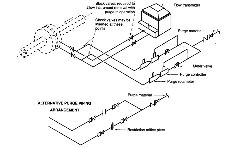
Typical Purging Installation
Below we can see typical purging installation.
Interest to add any further points? Share with us through below comments section.
Author: Kalpit Patel