Inst ToolsInst ToolsInst Tools
  • Ask
  • Courses
  • Videos
  • Q & A
    • Interview
      • Instrumentation
      • Electronics
      • Electrical
      • Practical Questions
    • MCQ
      • Instrumentation MCQ
      • Electrical MCQ
      • Electronics MCQ
      • Control Systems MCQ
      • Analog Electronics MCQ
      • Digital Electronics MCQ
      • Power Electronics MCQ
      • Microprocessor MCQ
      • Multiple Choice Questions
  • EE
    • Electronics
      • Electronics Q & A
      • Electronic Basics
      • Electronic Devices & Circuits
      • Electronics Animation
      • Digital Electronics
    • Electrical
      • Electrical Basics
      • Electrical Q & A
      • Power Electronics
      • Electrical Machines
      • Electrical Animation
      • Power Systems
      • Switchgear & Protection
      • Transmission & Distribution
  • Measure
    • Control Valves
    • Calibration
    • Temperature
    • Pressure
    • Flow
    • Level
    • Analyzers
    • Switches
    • Vibration
    • Solenoid Valve
  • Control
    • PLC Tutorials
    • Control Systems
    • Safety Instrumented System (SIS)
    • Communication
    • Fire & Gas System
  • More
    • Design
    • Tools
    • Animation
    • Basics
    • Formulas
    • Standards
    • TextBooks
    • Common
    • Software
    • Excel Tools
    • Erection & Commissioning
    • Process Fundamentals
    • Videos
    • Books
Search
All rights reserved. Reproduction in whole or in part without written permission is prohibited.
Reading: Logic Gates
Share
Notification Show More
Font ResizerAa
Inst ToolsInst Tools
Font ResizerAa
  • Courses
  • PLC Tutorials
  • Control Systems
Search
  • Ask
  • Courses
  • Videos
  • Q & A
    • Interview
    • MCQ
  • EE
    • Electronics
    • Electrical
  • Measure
    • Control Valves
    • Calibration
    • Temperature
    • Pressure
    • Flow
    • Level
    • Analyzers
    • Switches
    • Vibration
    • Solenoid Valve
  • Control
    • PLC Tutorials
    • Control Systems
    • Safety Instrumented System (SIS)
    • Communication
    • Fire & Gas System
  • More
    • Design
    • Tools
    • Animation
    • Basics
    • Formulas
    • Standards
    • TextBooks
    • Common
    • Software
    • Excel Tools
    • Erection & Commissioning
    • Process Fundamentals
    • Videos
    • Books
Follow US
All rights reserved. Reproduction in whole or in part without written permission is prohibited.
Inst Tools > Blog > Digital Electronics > Logic Gates

Logic Gates

Last updated: August 5, 2017 5:15 am
Editorial Staff
Digital Electronics
3 Comments
Share
2 Min Read
SHARE

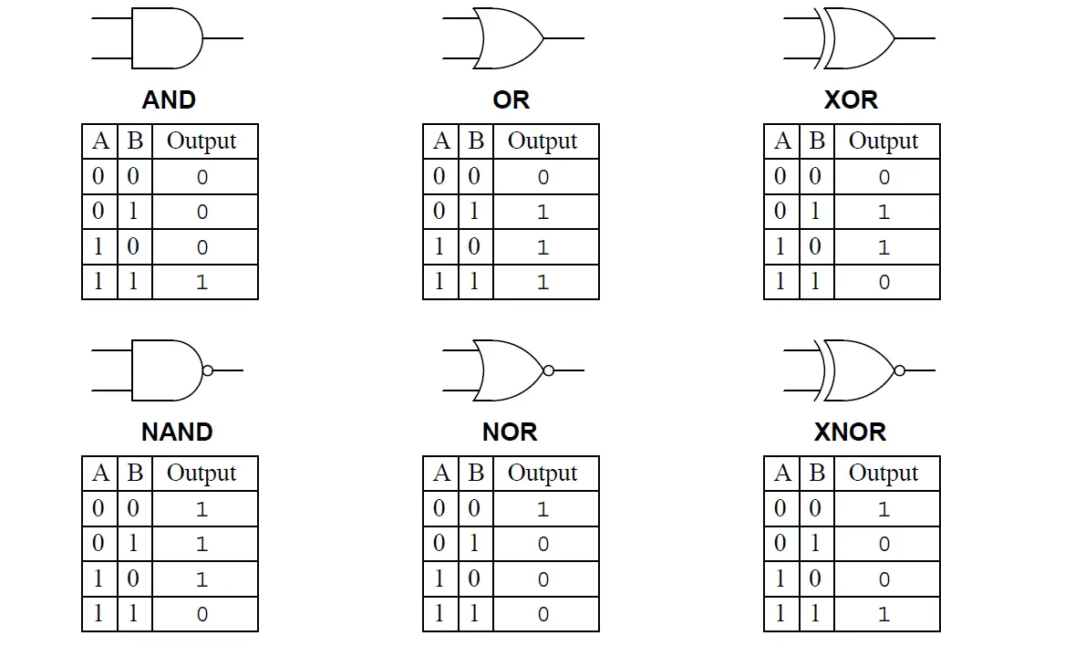
The word “discrete” means individual or distinct. In engineering, a “discrete” variable or measurement refers to a true-or-false condition. Thus, a discrete control system is one designed to operate on Boolean (“on” or “off”) signals supplied by discrete sensors such as process switches. A form of discrete control taught in every introductory course on digital electronics involves the use of circuits called logic gates. These circuits input one or more Boolean signals, and output a Boolean signal according to a simple rule such as “AND” or “OR”:

Digital Logic Gates TruthTables

Industrial control systems rarely utilize logic gates in a direct fashion for discrete control systems, although the fundamental concepts of “AND,” “OR,” and other gate types are universally applied. Instead, control functions are either implemented using electromechanical relays and/or with programmable digital devices such as PLCs (Programmable Logic Controllers).

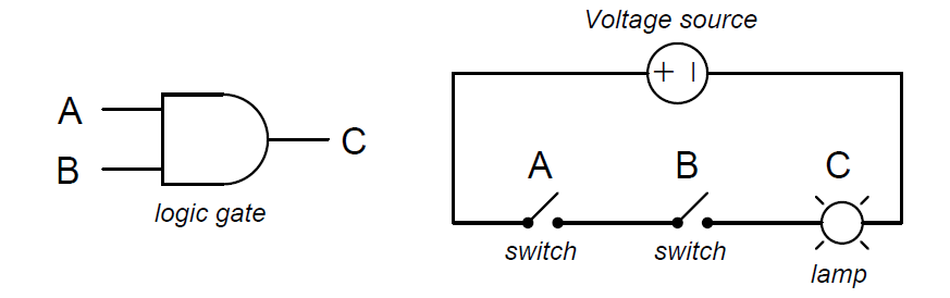
An “AND” function is equivalent to series-connected normally-open contacts in a relay control circuit, because the lamp will energize only if switch A and switch B are actuated:

AND Gate Equivalent Circuit

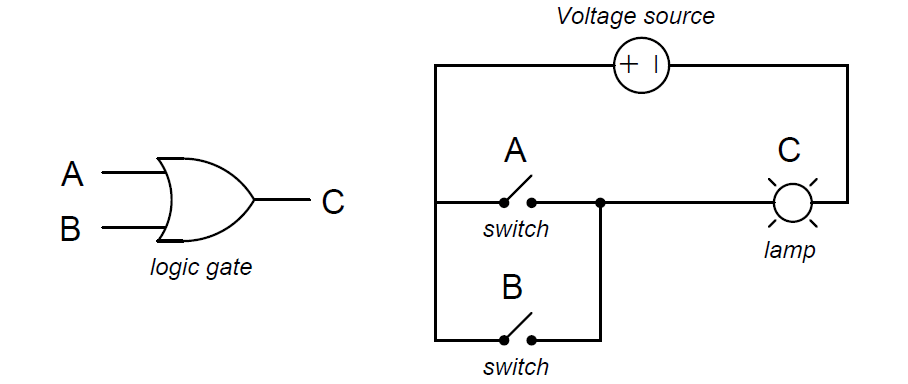
An “OR” function is equivalent to parallel-connected normally-open contacts in a relay control circuit, because the lamp will energize if switch A or switch B is actuated:

OR Gate Equivalent Circuit

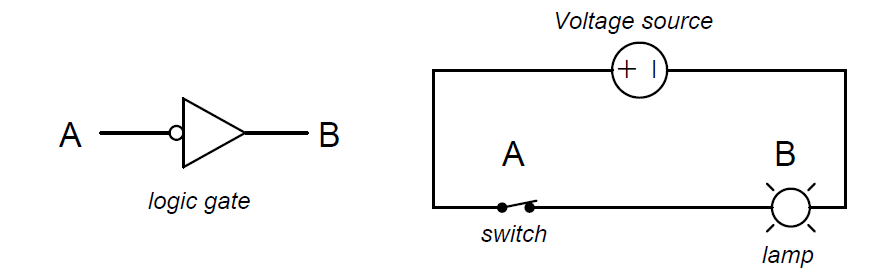
The “NOT” function is equivalent to a single normally-closed contact in a relay control circuit, because the lamp will energize only if the switch is not actuated:

NOT Gate Equivalent Circuit

Don't Miss Our Updates
Be the first to get exclusive content straight to your email.
We promise not to spam you. You can unsubscribe at any time.
Invalid email address
You've successfully subscribed !
Logic Gates in PLC Ladder Logic
Difference Between Combinational and Sequential Circuit
Code Converters Objective Questions
How a Gate Works ?
Top 100 Digital Electronics Project Ideas for Engineering Students
Share This Article
Facebook Whatsapp Whatsapp LinkedIn Copy Link
Share
3 Comments
  • leon says:
    January 19, 2021 at 3:28 pm

    good work though you should explain further in order to be understood well

    Reply
  • Rashika gurung says:
    November 22, 2021 at 3:29 pm

    It’s very nice answer . Thanks a lot??

    Reply
  • Mohammad Bashnak says:
    August 19, 2023 at 2:10 pm

    Thanks alot iam realy injoyed when iread isee
    How is electronics and
    Automation is easing the
    Work especially when iam
    Compared to the time iuse
    To make automation my self iam 70 years old

    Reply

Leave a Reply Cancel reply

Your email address will not be published. Required fields are marked *

Stay Connected

128.3kFollowersLike
69.1kFollowersFollow
208kSubscribersSubscribe
38kFollowersFollow

Categories

Recent Comments

  • Guifty Shimica on Top Non-PLC Certification Courses for Automation Professionals
  • Guifty Shimica on Top Non-PLC Certification Courses for Automation Professionals
  • MIHARITSOA Aina Sitraka on Top Non-PLC Certification Courses for Automation Professionals
  • Vaishnavi on Free Instrumentation Course for Trainee Engineers

Related Articles

AND Gate Logic Animation

Digital Building Blocks – GATES

More Articles

Electrical Machines Questions and Answers

Synchronous Machines Power Factor Control Questions

Objective Questions of Building Fire and Gas Detectors

Objective Questions of Building Fire and Gas Detectors

Design a PLC program for Operational Sequence of Packaging Process

Design a PLC program for Operational Sequence of Packaging Process

Advantages and Disadvantages of Network Topology

Advantages and Disadvantages of Per Unit System

Actuator Sensor Interface (ASi) Protocol in PLC

Actuator Sensor Interface (ASi) Protocol in PLC

How to Download Rslogix Free

Download Allen Bradley RSLogix PLC Software

SCADA in Cloud

Cloud-Based SCADA Projects – Try Free Demo Account

Analog Measurement using Ladder Logic

Analog Measurement using Ladder Logic

Follow US
All rights reserved. Reproduction in whole or in part without written permission is prohibited.
Welcome Back!

Sign in to your account

Username or Email Address
Password

Lost your password?