Inst ToolsInst ToolsInst Tools
  • Ask
  • Courses
  • Videos
  • Q & A
    • Interview
      • Instrumentation
      • Electronics
      • Electrical
      • Practical Questions
    • MCQ
      • Instrumentation MCQ
      • Electrical MCQ
      • Electronics MCQ
      • Control Systems MCQ
      • Analog Electronics MCQ
      • Digital Electronics MCQ
      • Power Electronics MCQ
      • Microprocessor MCQ
      • Multiple Choice Questions
  • EE
    • Electronics
      • Electronics Q & A
      • Electronic Basics
      • Electronic Devices & Circuits
      • Electronics Animation
      • Digital Electronics
    • Electrical
      • Electrical Basics
      • Electrical Q & A
      • Power Electronics
      • Electrical Machines
      • Electrical Animation
      • Power Systems
      • Switchgear & Protection
      • Transmission & Distribution
  • Measure
    • Control Valves
    • Calibration
    • Temperature
    • Pressure
    • Flow
    • Level
    • Analyzers
    • Switches
    • Vibration
    • Solenoid Valve
  • Control
    • PLC Tutorials
    • Control Systems
    • Safety Instrumented System (SIS)
    • Communication
    • Fire & Gas System
  • More
    • Design
    • Tools
    • Animation
    • Basics
    • Formulas
    • Standards
    • TextBooks
    • Common
    • Software
    • Excel Tools
    • Erection & Commissioning
    • Process Fundamentals
    • Videos
    • Books
Search
All rights reserved. Reproduction in whole or in part without written permission is prohibited.
Reading: Creepage Distance for Insulators in Substation
Share
Notification Show More
Font ResizerAa
Inst ToolsInst Tools
Font ResizerAa
  • Courses
  • PLC Tutorials
  • Control Systems
Search
  • Ask
  • Courses
  • Videos
  • Q & A
    • Interview
    • MCQ
  • EE
    • Electronics
    • Electrical
  • Measure
    • Control Valves
    • Calibration
    • Temperature
    • Pressure
    • Flow
    • Level
    • Analyzers
    • Switches
    • Vibration
    • Solenoid Valve
  • Control
    • PLC Tutorials
    • Control Systems
    • Safety Instrumented System (SIS)
    • Communication
    • Fire & Gas System
  • More
    • Design
    • Tools
    • Animation
    • Basics
    • Formulas
    • Standards
    • TextBooks
    • Common
    • Software
    • Excel Tools
    • Erection & Commissioning
    • Process Fundamentals
    • Videos
    • Books
Follow US
All rights reserved. Reproduction in whole or in part without written permission is prohibited.
Inst Tools > Blog > Switchgear & Protection > Creepage Distance for Insulators in Substation

Creepage Distance for Insulators in Substation

Last updated: September 19, 2016 2:16 am
Editorial Staff
Switchgear & Protection
No Comments
Share
2 Min Read
SHARE

Creepage Distance for Insulators:

The creepage distance for insulators is the shortest distance along the insulator surface between the metal parts at each end of the insulator. Creepage distance can also be refer as leakage distance for insulators.

Insulators in substation are provided to avoid any leakage current from live electrical conductors to flow to the earth through supports. The atmospheric dust sticks to the insulator surface forming a conducting layer. The leakage current flows from the live conductor to the earth through such surface layers. The leakage properties (creepage properties) of an insulator s in substation are characterized by the length of the leakage path. While designing the insulator sheds, the leakage distance for insulators requirement should be satisfied. The requirement of the leakage distance or creepage distance for insulators depends on the

  • Rated phase to ground voltage
  • Degree of atmospheric pollution

If the surface of the insulator is clean, smooth and well gazed the dust particles tend to fall down. When an a.c voltage is applied to the apparatus, the dust particles have a tendency to align to the direction of electrical field lines on the surface of the insulator. If the surface of the insulator is rough and moist this alignment will be faster. The continuous application of voltage causes slow alignment of these particles. To prevent a continuous conducting track, the insulator should have sufficient ceepage distance or leakage distance.

Creepage Distance for Insulators in Substation

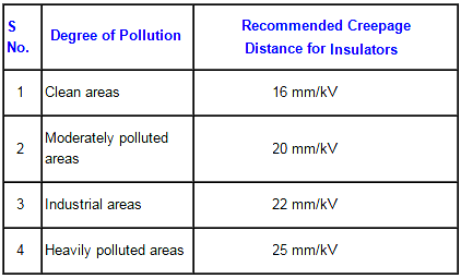
During power frequency withstand test of an unclean insulator, the flash-over occurs along the dirty surface of the insulator. In case of internal gas filled or oil filled apparatus, the internal surface should also be free from moisture and dust. Otherwise internal flash over can occur along the surface by tracking. Some of the typical creepage distance for insulators in substation provided based on the level of pollution are tabulated.

Don't Miss Our Updates
Be the first to get exclusive content straight to your email.
We promise not to spam you. You can unsubscribe at any time.
Invalid email address
You've successfully subscribed !
Sulfur Hexafluoride Gas (SF6) Properties
Methods to Reduce Step Potential and Touch Potential in Substation
Advantages & Disadvantages of Oil Circuit Breakers
Functions of Instrument Transformers (CTs and PTs)
Advantages & Disadvantages Electromagnetic Relays
Share This Article
Facebook Whatsapp Whatsapp LinkedIn Copy Link
Share
Leave a Comment

Leave a Reply Cancel reply

Your email address will not be published. Required fields are marked *

Stay Connected

128.3kFollowersLike
69.1kFollowersFollow
208kSubscribersSubscribe
38kFollowersFollow

Categories

Recent Comments

  • Kamli on Top Free PLC Software
  • Guifty Shimica on Top Non-PLC Certification Courses for Automation Professionals
  • Guifty Shimica on Top Non-PLC Certification Courses for Automation Professionals
  • MIHARITSOA Aina Sitraka on Top Non-PLC Certification Courses for Automation Professionals

Related Articles

Substation Safety Clearances

Substation Safety Clearances

Step and Touch Potential

What Is Step and Touch Potential and Reducing Resistance To Ground?

Advantages and Disadvantages of Network Topology

Advantages and Disadvantages of Air Blast Circuit Breakers

More Articles

How to Use SMD Components in Electronic Circuits

How to Use SMD Components in Electronic Circuits?

plc-analog-signals-wiring-techniques

PLC Analog Signals Wiring Techniques

Solenoid-Valve-Working-Animation

Solenoid Valve Working Animation

Difference Between HV and LV Cables

Difference Between HV and LV Cables

Troubleshooting a Biased Transistor

Troubleshooting a Biased Transistor

types-of-total-organic-carbon

Basics of Total Organic Carbon (TOC) Analyzers

HMI screen for operator

Auto Tiffin Box Filling Station

Star-Delta PLC programming with 1 button

How to Program a Star-Delta System using 1 Button in PLC?

Follow US
All rights reserved. Reproduction in whole or in part without written permission is prohibited.
Welcome Back!

Sign in to your account

Username or Email Address
Password

Lost your password?