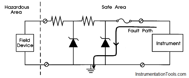
The zener diode barrier works by diverting potentially dangerous energy to ground before it can reach the hazardous area.
Zener Diode Barrier Principle

The zener diodes limit the fault voltage to the hazardous area. There are two such diodes for redundancy. The series resistor limits current to the hazardous area, and is considered an infallible component.
The arrow in above Figure shows the resultant path if excess current enters the barrier as a result of excess voltage input from the instrument.
Since a zener barrier is powered by the loop and it has a current limiting resistor, it has a voltage drop across it. This barrier, in addition to protecting against dangerous energy entering the hazardous area, must allow the loop to function normally.
Example :
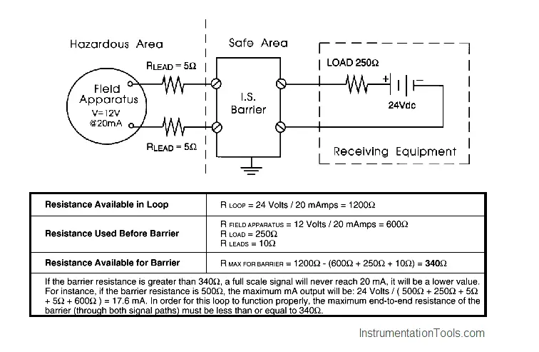
The example in Below Figure, shows a 24 V, 4-20 mA transmitter loop. In this example, the sum of the voltage drops around the loop can be calculated and verified that they are less than 24 V.
Instead, since the maximum resistance of the barrier is specified (RMAX END TO END), Ohm’s law is used (V = IR) to calculate the total resistance available in the loop. Either method (loop voltage or loop resistance) works identically.
What we are trying to decide is whether or not the resistance of the barrier will adversely affect the loop.

Resistance of zener barrier adversely affects this 24V, 4-20mA transmitter loop ? Not, if it is less than 340 Ω
Grounding :
When using zener barriers, the dangerous energy is diverted to ground. Therefore, it is important to ensure a high quality intrinsic safety ground.
In fact, because this grounding is so critical, two separate ground connections from each barriers are recommended, each with a resistance of less than 1 ohm.
The following rules should be adhered to for I.S. grounding:
- Since zener diode barriers work by diverting fault currents, they must have a good quality ground.
- The impedance of the conductor from the barrier ground bus to the ground connection should be less than 1 ohm.
- Follow local codes.
- Ground cables should be insulated.
- Ground cables should be protected mechanically if there is a risk of damage.
- Ground cable should be an uninterrupted run to the nearest high integrity earth point.
- Redundant cables are advisable.