Let’s study the working of up down counter instruction function in Siemens PLC programming.
Up Down Counter
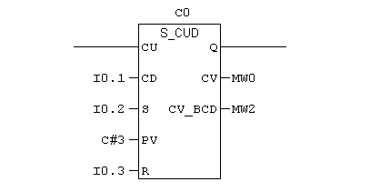
UP DOWN Counter instruction is used to counting up/down function.CU input is used to get counter enable Bool input. CD input is used to get counter enable bool input.
S input is used to get the set input, once S input changes from 0 to 1, counter accumulator value changes to 999, which is counter’s higher limit.
PV is word input where you can give preset value with the format of C#.R input is the reset Bool input’s output is used to get counter enable output. CV and CV_BCD used to get the counter’s accumulator value in integer format and BCD format.
Up Function Ladder Logic
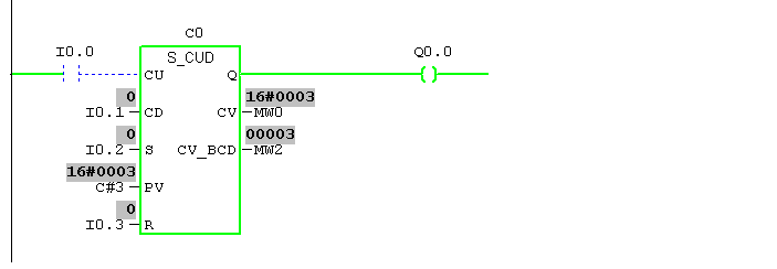
Input I0.0 is pressed, counter C0 counts one and enabling Q’s output Q0.0. Even if you turn off I0.0, Q0.0 remains in the ON state until reset.I0.0 is pressed trice, the accumulator value is 3.
Note: In Siemens, Counter will not stop counting once the accumulator meets preset, it will continue counting whenever it gets signal for CU input.
Down Function Ladder Logic
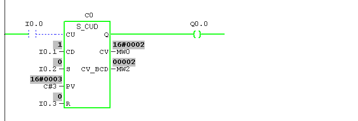
Input I0.1 is pressed, counter C0 counts one down Q0.0 remains in the ON state until reset or accumulator reaches zero.
Note: In Siemens, down Counter will stop counting once the accumulator meets zero, it will not continue counting done even it gets signal for CD input.
Ladder Logic
Stopping counter function when accumulator reaches preset
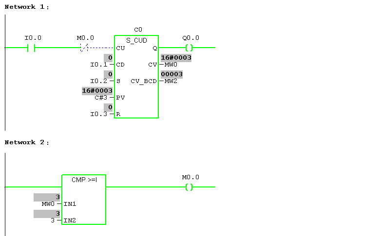
Network 1:
I0.0 is pressed trice, the accumulator value is 3.M0.0 is a memory address that gets enable once MW0 reaches 3.
Network 2:
Counter accumulator value stored in MW0 is comparing with 3 using greater than or equal to block to turn on memory M0.0.
Note: By using the above method, we can restrict the counter to count after the preset value. Else it will be reaching the higher limit 999.
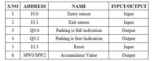
Car Parking Example
Let’s use this up-down counter in car parking example:
In a parking slot, the entry sensor is used to count cars which are entering and exit sensor will count exiting, Total number of car possible to park inside slot is three. Indication light is there to indicate parking is open and closed.
IO List
Logic
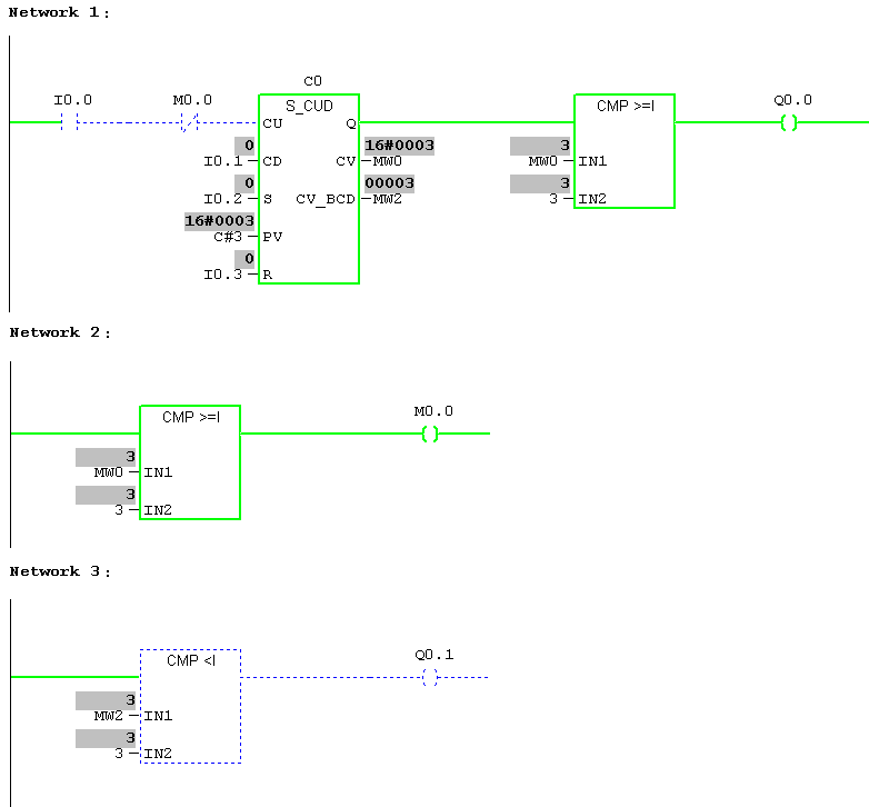
Network 1:
I0.0 is the entry sensor which is detecting car coming inside and counting up function is happening; in the above rung, it is shown like three cars were sent.
Parking is full indication (Q0.0) is ON.M0.0 is used to restrict the counter to count more than preset.
Network 2:
Greater than equal to Comparator is used to restrict the counter to count more than the preset value. ROL is received in M0.0
Network 3:
Less than Comparator is used to compare the number of car entering is within the limit.Q0.1 is the indication for parking is open.
Author: Hema Sundaresan
If you liked this article, then please subscribe to our YouTube Channel for PLC and SCADA video tutorials.
You can also follow us on Facebook and Twitter to receive daily updates.
Read Next:
- OFF Delay Timer using PLC
- Retentive ON Delay Timer
- Pulse Timer Instruction
- ON Delay Timer using PLC
- OFF versus ON Delay Timers
Good morning, I0.2 isn’t in the IO List