Perhaps the simplest form of sensor providing process information for a safety instrumented function is a process switch.
Examples of process switches include temperature switches, pressure switches, level switches, and flow switches.
SIS sensors must be properly calibrated and configured to indicate the presence of a dangerous condition. They must be separate and distinct from the sensors used for regulatory control, in order to ensure a level of safety protection beyond that of the basic process control system.
Referring to the clothes dryer and domestic water heater over-temperature shutdown switches, these high-temperature shutdown sensors are distinctly separate from the regulatory (temperature controlling) sensors used to maintain the appliance’s temperature at setpoint.
As such, they should only ever spring into action in the event of a high-temperature failure of the basic control system.
That is, the over-temperature safety switch on a clothes dryer or a water heater should only ever reach its high-temperature limit if the normal temperature control system of the appliance fails to do its job of regulating temperature to normal levels.
SIS Sensors
Industrial Safety Instrumented Systems (SIS) always use dedicated transmitters and/or process switches to detect abnormal process conditions.
As a rule, one should always use independent sensors for safety shutdown, and never rely on the regulatory control sensor(s) for safety functions. In the electric power industry we see this same segregation of functions: separate instrument transformers (PTs and CTs) are used to sense line voltage and line current for metering and control (regulatory) versus for protective relay (safety shutdown) equipment. It would be foolish to depend on one sensor for both functions.
We see this general rule applied even in home appliances such as electric water heaters: the safety shutdown temperature switch is a separate component from the thermostat switch used to regulate water temperature. This way, a failure in the regulatory sensor does not compromise the integrity of the safety function.
A modern trend in safety instrumented systems is to use continuous process transmitters rather than discrete process switches to detect dangerous process conditions.
Any process transmitter – analog or digital – may be used as a safety shutdown sensor if its signal is compared against a “trip” limit value by a comparator relay or function block. This comparator function provides an on-or-off (discrete) output based on the transmitter’s signal value relative to the trip point.
A simplified example of a continuous transmitter used as a discrete alarm and trip device is shown here, where analog comparators generate discrete “trip” and “alarm” signals based on the measured value of liquid in a vessel.
Note the necessity of two level switches on the other side of the vessel to perform the same dual alarm and trip functions:

Benefits to using a continuous transmitter instead of discrete switches include the ability to easily change the alarm or trip value, and better diagnostic capability.
The latter point is not as obvious as the former, and deserves more explanation. A transmitter continuously measuring liquid level will produce an output signal that varies over time with the measured process variable.
A “healthy” transmitter should therefore exhibit a continuously changing output signal, proportional to the degree of change in the process.
Discrete process switches, in contrast to transmitters, provide no indication of “healthy” operation. The only time a process switch should ever change states is when its trip limit is reached, which in the case of a safety shutdown sensor indicates a dangerous (rare) condition.
A process switch showing a “normal” process variable may indeed be functional and indicating properly, but it might also be failed and incapable of registering a dangerous condition should one arise – there is no way to tell by monitoring its un-changing status. The continuously varying output of a process transmitter therefore serves as an indicator (Note 1) of proper function.
Note 1 : Of course, the presence of some variation in a transmitter’s output over time is no guarantee of proper operation. Some failures may cause a transmitter to output a randomly “walking” signal when in fact it is not registering the process at all. However, being able to measure the continuous output of a process transmitter provides the instrument technician with far more data than is available with a discrete process switch.
A safety transmitter’s output signal may be correlated against the output signal of another transmitter measuring the same process variable, perhaps even the transmitter used in the regulatory control loop.
If two transmitters measuring the same process variable agree closely with one another over time, chances are extremely good are both functioning properly.
In applications where Safety Instrumented Function (SIF) reliability is paramount, redundant transmitters may be installed to yield additional reliability.
The following photograph shows triple redundant transmitters measuring liquid flow by sensing differential pressure dropped across an orifice plate:

A single orifice plate develops the pressure drop, with the three differential pressure transmitters “tubed” in parallel with each other, all the “high” side ports connected together through common (Note 2) impulse tubing and all the “low” side ports connected together through common impulse tubing.
These particular transmitters happen to be FOUNDATION Fieldbus rather than 4-20 mA analog electronic. The yellow instrument tray cable (ITC) used to connect each transmitter to a segment coupling device may be clearly seen in this photograph.
Note 2 : It should be noted that the use of a single orifice plate and of common (parallel-connected) impulse lines represents a point of common-cause failure. A blockage at one or more of the orifice plate ports, or a closure of a manual block valve, would disable all three transmitters. As such, this might not be the best method of achieving high flow- measurement reliability.
The “trick” to using redundant transmitters is to have the system self-determine what the actual process value is in the event one or more of the redundant transmitters disagree with each other.
Voting is the name given to this important function, and it often takes the form of signal selector functions:
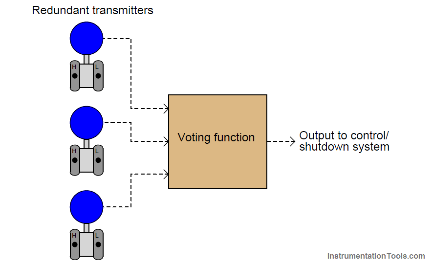
Multiple selection criteria are typically offered by “voting” modules, including high, low, average, and median.
A “high” select voter would be suitable for applications where the dangerous condition is a large measured value, the voting module selecting the highest-valued transmitter signal in an effort to err on the side of safety.
This would represent a 1oo3 safety redundancy (since only one transmitter out of the three would have to register beyond the high trip level in order to initiate the shutdown).
A “low” select voter would, of course, be suitable for any application where the dangerous condition is a small measured value (once again providing a 1oo3 safety redundancy).
The “average” selection function merely calculates and outputs the mathematical average of all transmitter signals – a strategy prone to problems if one of the redundant transmitters happens to fail in the “safe” direction (thus skewing the average value away from the “dangerous” direction and thereby possibly causing the system to respond to an actual dangerous condition later than it should).
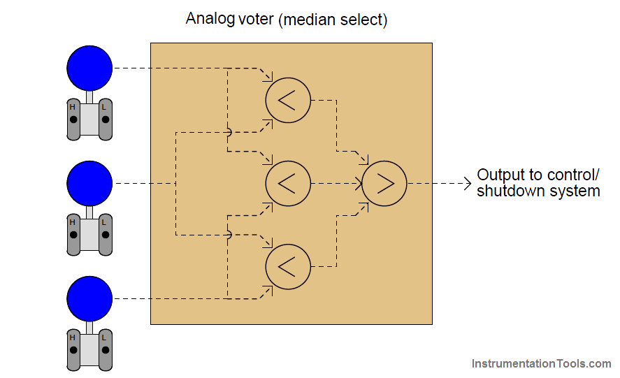
The median select criterion is very useful in safety systems because it effectively ignores any measurements deviating substantially from the others.
Median selector functions may be constructed of high- and low-select function blocks in either of the following (Note 3) manners:
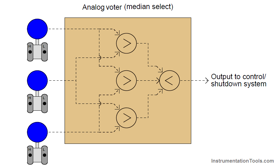
Note 3: The best way to prove to yourself the median-selecting abilities of both function block networks is to perform a series of “thought experiments” where you declare three arbitrary transmitter signal values, then follow through the selection functions until you reach the output.
For any three signal values you might choose, the result should always be the same: the median signal value is the one chosen by the voter.
Three transmitters filtered through a median select function effectively provide a 2oo3 safety redundancy, since just a single transmitter registering a value beyond the safety trip point would be ignored by the voting function.
Two or more transmitters would have to register values past the trip point in order to initiate a shutdown.
It should be stressed that redundant transmitter strategies are only effective if the transmitters all sense the exact same process variable, and if their failure modes are independent (i.e. no common cause failure modes exist).
If, for example, a set of redundant transmitters are attached to the process at different points such that they may legitimately sense different measurement values, the effectiveness of their redundancy will be compromised.
Similarly, if a set of redundant transmitters are susceptible to failure from a shared condition (e.g. multiple liquid level transmitters that may be fooled by changes in process fluid density), then reliability will suffer.