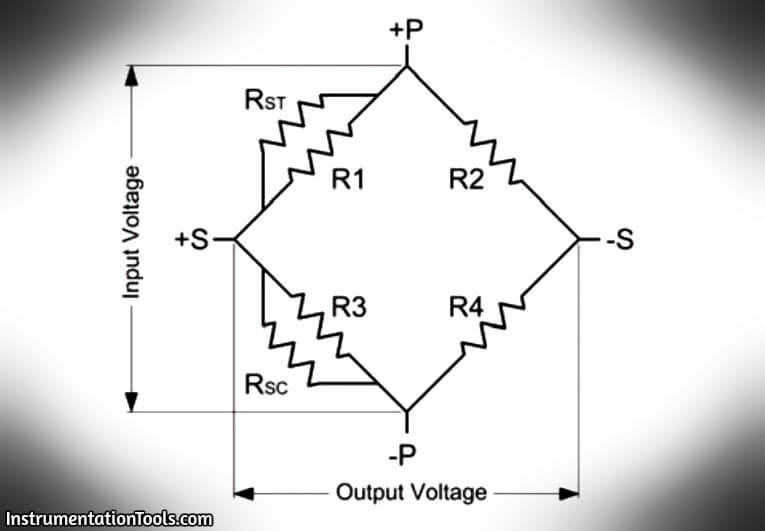
Shunt calibration is the known electrical unbalancing of a strain gauge bridge by means of a fixed resistor that is placed, or “shunted,” across one leg of the bridge.
The Wheatstone Bridge used in strain gauge load cells are typically field-calibrated using the shunt calibration technique.
Shunt calibration is a method of periodically checking the gain or span of a signal conditioner, which is used in conjunction with a strain gauge based transducer, without exposing the transducer to known, traceable, physical input values.
If required, adjustments can then be made to the signal conditioner to insure accurate measurement results
A strain gauge bridge is “in balance” when the host mechanical structure is unloaded and unstressed.
As the host structure (diaphragm, bending beam, shear beam, column, etc.) is loaded or stressed, the Wheatstone Bridge becomes unbalanced, resulting in an output signal that is proportional to the applied load.

Fig : A Wheatstone Bridge circuit showing the location for connecting the appropriate shunt resistor for the purpose of simulating either a tension or compression input.
Shunt calibration stimulates the mechanical input to a transducer by unbalancing the bridge with a fixed resistor placed across, or in parallel with, one leg of the bridge.
For tension shunt calibration, the shunt resistor (RST) is shunted across the +excitation (+P) and +signal (+S) leg of the bridge.
For a compression shunt calibration, the shunt resistor (RSC) is shunted across the – excitation (-P) and +signal (+S) leg of the bridge.
Calibration Procedure :
Here are step-by-step instructions for shunt calibration of a strain gauge load cell.
1. Connect the transducer to an appropriate strain gauge signal conditioner and allow adequate time for the system to stabilize.
2. Apply a full-scale N.I.S.T. traceable, mechanical input (or load) to the transducer.
3. Adjust the signal conditioner’s gain or span controls, as required, to obtain a full-scale electrical output signal, and/or numeric display that represents the applied, mechanical input quantity.
4. Remove the mechanical input (or load).
5. Place a shunt calibration resistor across an appropriate leg of the Wheatstone Bridge (as discussed above).
6. Record the value of the signal conditioner’s output signal and/or numeric display. This value is the shunt calibration value, or equivalent load.
7. It is important to note that the shunt calibration value is specific for the particular shunt resistor used.This value, and the particular resistor, are now matched to the transducer and form the basis of the transferable shunt calibration.
Summary
Shunt calibration is accepted throughout the industry as means of periodic calibration of a signal conditioner and transducer between calibrations of known, applied, traceable, mechanical, input values.
Consequently, most all strain gauge transducer manufacturers collect and supply shunt calibration data, along with a shunt calibration resistor, as a standard feature.
Source : PCB Load & Torque Division