An “override” control strategy involves a selection between two or more controller output signals, where only one controller at a time gets the opportunity to exert control over a process. All other “de-selected” controllers are thus overridden by the selected controller.
The general concept of override control is easily understood by appeal to a human example. Cargo truck drivers must monitor and make control decisions on a wide number of variables, including diesel engine operating parameters and road rules.
A truck driver needs to keep a close watch on the exhaust gas temperature of the truck engine: a leading indicator of impending engine damage (if exhaust temperature exceeds a pre-determined limit established by the engine manufacturer).
The same truck driver must also drive as fast as the law will allow on any given road in order to minimize shipping time and thereby maximize the amount of cargo transported over long periods of time.
These two goals may become mutually exclusive when hauling heavy cargo loads up steep inclines, such as when ascending a mountain pass. The goal of avoiding engine damage necessarily overrides the goal of maintaining legal road speed in such conditions.
Imagine a diesel truck driver maintaining the legal speed limit on a highway, occasionally glancing at the EGT (Exhaust Gas Temperature) indicator in the instrument panel. Under normal operating conditions, the EGT should be well below the danger threshold for the engine.
However, after pulling a full load up a mountain pass and noticing the EGT approach the high operating limit, the truck driver makes the decision to regulate the engine’s power based on EGT rather than road speed. In other words, the legal speed limit is no longer the “setpoint” to control to, and EGT now is.
If we were to model the truck driver’s decision-making processes in industrial instrumentation terms, it would look something like this:
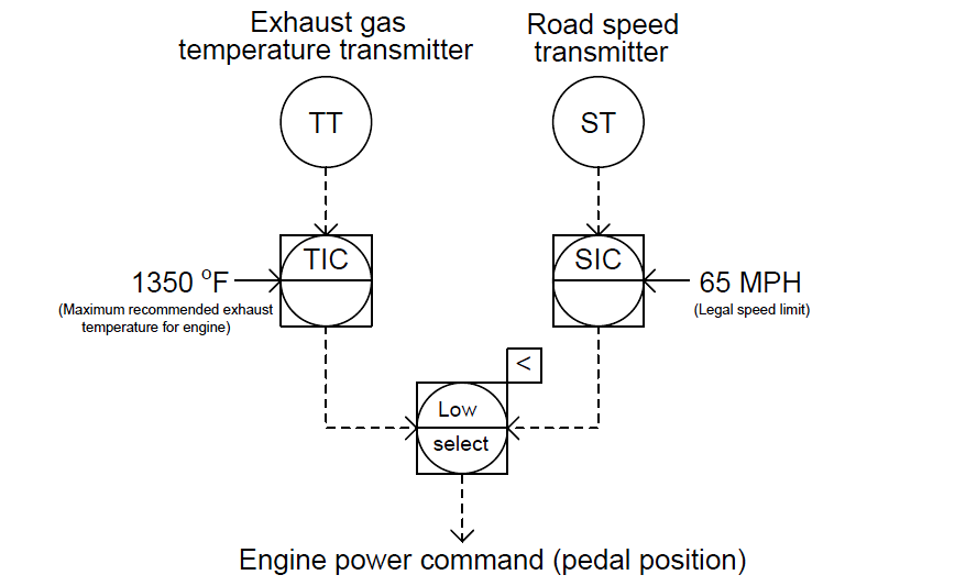
Which ever control decision calls for the least engine power output, “wins the vote” to control the engine’s power.
As is the case with limit and selector control strategies, a “select” function is used to choose one signal from multiple signals. The difference here is that the signals being selected are both controller outputs rather than transmitter (measurement) or setpoint signals. Both controllers are still active, but only one at a time will have any actual control over the process.
This model maps well to the truck driver analogy. Despite having “overridden” the goal of maintaining legal road speed in favor of maintaining a safe engine exhaust temperature, the driver is still thinking about road speed.
In fact, if the driver happens to be behind schedule, you can be absolutely sure the goal of maintaining the highway speed limit has not been forgotten! In fact, the driver may become impatient as the long incline wears on, eager to make up lost time as soon as the opportunity allows.
This is a potential problem for all override control systems: making sure the de-selected controller does not “wind up” (with integral action still active) while it has no control over the process.
An municipal example of override control is seen in this water pumping system, where a water pump is driven by a variable-speed electric motor to draw water from a well and provide constant water pressure to a customer:
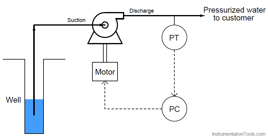
Incidentally, this is an excellent application for a variable-speed motor as the final control element rather than a control valve. Reducing pump speed in low-flow conditions will save a lot of energy over time compared to the energy that would be wasted by a constant-speed pump and control valve.
A potential problem with this system is the pump running “dry” if the water level in the well gets too low, as might happen during summer months when rainfall is low and customer demand is high. If the pump runs for too long with no water passing through it, the seals will become damaged. This will necessitate a complete shut-down and costly rebuild of the pump, right at the time customers need it the most.
One solution to this problem would be to install a level switch in the well, sensing water level and shutting off the electric motor driving the pump if the water level ever gets too low:
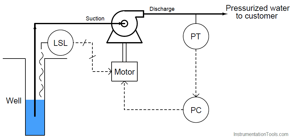
This may be considered a kind of “override” strategy, because the low-level switch over-rides the pressure controller’s command for the pump to turn. It is also a crude solution to the problem, for while it protects the pump from damage, it does so at the cost of completely shutting off water to customers.
One way to describe this control strategy would be to call it a hard override system, suggesting the uncompromising action it will take to protect the pump.
A better solution to the dilemma would be to have the pump merely slow down as the well water level approaches a low-level condition. This way at least the pump could be kept running (and some amount of pressure maintained), decreasing demand on the well while maintaining curtailed service to customers and still protecting the pump from dry-running. This would be termed a soft override system.
We may create just such a control strategy by replacing the well water level switch with a level transmitter, connecting the level transmitter to a level controller, and using a low-select relay or function block to select the lowest-valued output between the pressure and level controllers.
The level controller’s setpoint will be set at some low level above the acceptable limit for continuous pump operation:
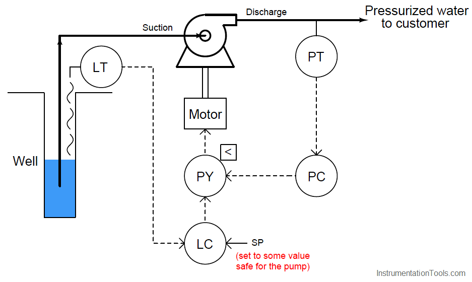
If ever the well’s water level goes below this setpoint, the level controller will command the pump to slow down, even if the pressure controller is calling for a higher speed. The level controller will have overridden the pressure controller, prioritizing pump longevity over customer demand.
Bear in mind that the concept of a low-level switch completely shutting off the pump is not an entirely bad idea. In fact, it might be prudent to integrate such a “hard” shutdown control in the override control system, just in case something goes wrong with the level controller (e.g. an improperly adjusted setpoint or poor tuning) or the low-select function.
With two layers of safety control for the pump, this system provides both a “soft constraint” providing moderated action and a “hard constraint” providing aggressive action to protect the pump from dry operation:
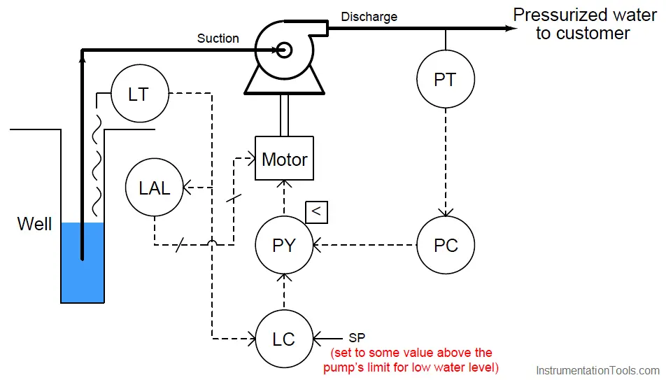
In order that these two levels of pump protection work in the proper order, the level controller’s (LC) setpoint needs to be set to a higher value than the low level alarm’s (LAL) trip point.
A very important consideration for any override control strategy is how to manage integral windup. Any time a controller with any integral (reset) action at all is de-selected by the selector function, the integral term of the controller will have the tendency to wind up (or wind down) over time. With the output of that controller de-coupled from the final control element, it can have no effect on the process variable.
Thus, integral control action
– the purpose of which being to constantly drive the output signal in the direction necessary to achieve equality between process variable and setpoint – will work in vain to eliminate an error it cannot influence. If and when control is handed back to that controller, the integral action will have to spend time “winding” the other way to un-do what it did while it was de-selected. Thus, override controls demand some form of integral windup limits that engage when a controller is de-selected.
Also Read : Limit Controls : High Limit & Low Limit Functions