Measurement principle
A radar transmitter should be mounted on the top of a tank, chamber/cage or standpipe. The transmitter sends out microwaves via the antenna, which then travel down to the product surface.
At the product surface, they are reflected back to the antenna of the radar transmitter. The propagation velocity of microwaves in free space is the speed of light (~300,000 km/s).
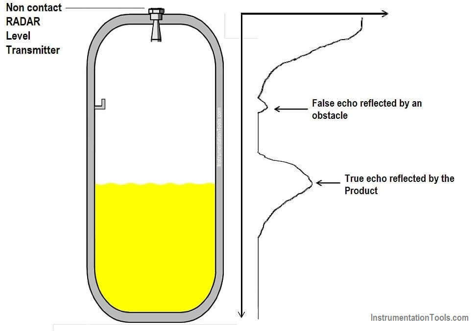
Figure – Radar measurement principle
Two different principles are used to measure the extremely short transmission times: Frequency Modulated Continuous Wave (FMCW) and pulse technology.
The FMCW method emits microwaves continuously over a narrow frequency sweep. The frequency of the return reflection is slightly different from the frequency currently being transmitted, and the frequency difference is proportional to the distance.
Because of multiple reflections, there are several signals mixed together. Therefore an FFT calculation has to be done internally by the radar transmitter to determine all the different single frequencies.
This information is used to calculate an echo curve, from which the system can calculate the distance.
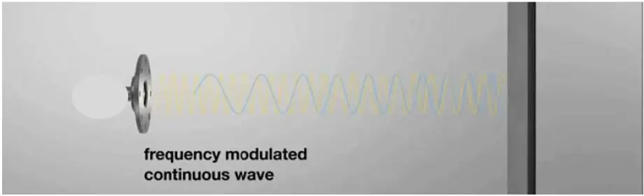
Figure – Radar FMCW principle
The method consists of the emission of microwave energy pulse. The time that needs to receive a return reflection is measured.
This time is the image of the level (i.e. level = velocity × time). Because of the high propagation speed (300,000 km/s) the radar transmitter can repeat this several million times in a second without having any interference between the individual signals.
These signals are periodical. So the sensor sees the same echo curve several million times during one second.
A special sampling method makes it possible to expand the time of this fast echo curve into a slower time range.
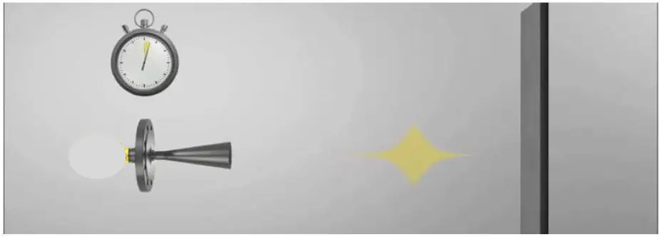
Figure – Radar pulse principle
FMCW and pulse technologies produce the same result: an echo curve. In the past, the lower power consumption of ‘pulse’ technology has been an advantage for building a loop‐powered radar transmitter.
Nowadays, both technologies deliver the same performance. There are no longer any major differences between these two measuring principles when it comes to accuracy, dynamic range, measuring range or response time.
Radar transmitters are available with different operating frequencies. For the measurement of liquids, there are low frequencies (between 4.5 – 10 GHz) sensors and high frequency (24 – 27 GHz) sensors.
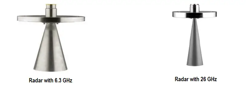
Note: The higher radar frequency is, the narrower the radar bean angle of the sensor is.
For example, with a 26 GHz radar and an antenna aperture of 80 mm the beam angle is about 12°. With 79 GHz radar and an antenna aperture of 80 mm the beam angle is only about 4°.
License
Local licensing requirements should be considered. Radar systems emit radio frequency energy; many countries require licensing under the communications regulatory agency when over some defined power level.
Limitations
Radar installations require consideration of vessel geometry, nozzle location and size. For that reason, the focusing (beam angle) of the antenna has to be taken into account. This is more a concern for transmitters with low frequencies (4.5 – 10 GHz) than for those with higher operating frequencies (24 – 27 GHz).
Internal obstructions such as heating coils, standpipes, agitators, etc. need to be considered. This is more a concern for transmitters with low frequencies (4.5 – 10 GHz) than for those with higher operating frequencies (24 – 27 GHz).
Installation and troubleshooting may require product manufacturer‐specific training and a laptop PC with product manufacturer software.
Pure ammonia, vinyl chloride or methyl chloride level cannot be measured with radar range of 24 – 27 GHz. This is due to the relevant gas vapour which damps the 24 to 27 GHz waves. For this application, radar within the 4.5 – 10 GHz can be used.
Heavy, thick foam has a substantial damping effect on microwaves. A particular attention should be paid to the foam formation during the design phase. If the process generates thick foam that results in excessive damping, radar is not recommended.
Consequently, it is not possible to recommend any specific frequency for foam application. Sensors with increased sensitivity for foam applications are available.
Radar transmitters can measure a gas–liquid interface but not a liquid–liquid interface.
If the dielectric constant (DC) of the product is lower than 1.4, it has to be taken in account to choose the sensor or the mounting which fits the application. The dielectric DC is the ratio of electric permittivity of the product to the free space permittivity.
The higher the dielectric constant, the stronger the signal reflected by the product. The dielectric constant of the product has less influence on the accuracy, because it changes only the amplitude and not the position of the echo on the echo curve, but more influence on the reliability of the measurement. See below Figure.
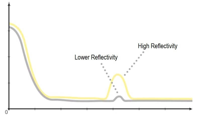
Figure – Radar with 26 GHz
With modern high quality radar, it is nowadays possible to measure even the products with the lowest dielectric constant like LNG/LPG in liquids.
For older or less sensitive radar transmitters, it might be required to install a stilling well to measure LNG/LPG. Some product manufacturers have models available with a special electronic.
This special electronic increases the sensitivity to allow the LNG/LPG measurement without a stilling well. In general, for products lower than DC <1.4, the product manufacturer’s recommendation should be required.
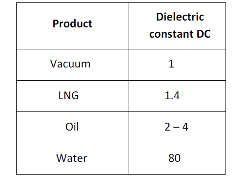
Table – Example of product dielectric constant
Note: Due to the low dielectric constant of some material, it’s possible to measure through plastic, glass or ceramic.
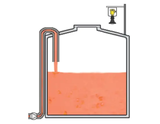
Figure – Radar measuring the level through the plastic vessel
Selection
Very strong turbulences on the product surfaces are able to reflect the microwaves in different directions. This will decrease the echo amplitude as well.
In very strong turbulences, like a reactor with a strong agitator this has to be considered for the mounting position of radar.
The radar transmitter should be positioned behind a baffle. This allows a very easy and repeatable measurement.
Whether Radar is used on turbulence surface a stilling well or sensor cage should be considered. Sensor cage or stilling well should minimum have same ID as radar horn diameter.
Vapour condensation and deposits can affect the radar measurement performance. In this case, necessary heat tracing and a round piece of PTFE may be installed in the mounting flange to prevent the accumulating on the radar gauge cone. A use of a purge may also be considered.
The use of a PTFE shield on the radar cone prevents corrosion.
Radar mounted directly on vessel which cannot be shut‐downed should be provided with isolation valves (full bore type).
Radar transmitters are available with a wide range of antenna designs and sizes for different applications.
Radar transmitters are available with different materials, seals and housings to fit the process conditions and environment.
Low frequency (4 – 10 GHz) is preferred when measuring in vapour and foam.
High frequency (above 25 GHz) is preferred in most other applications due to greater mounting flexibility. (A small beam angle is easier to install.)
High Frequency Microwaves are suitable for most application, have less installation considerations, have narrow beam angle avoids disturbances more easily and provide longer measuring range due to more focused energy.
Low Frequency Microwaves provide longer wave lengths which penetrate foam, heavy vapour and condensation more easily. Wide beam angle can in some cases pass disturbances more easily (when the disturbing echo is located directly under the radar).
Design
Different antenna sizes and types are available to fit with the hook up requirements.
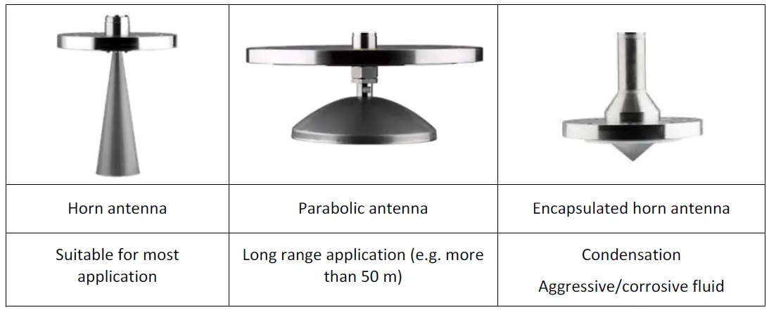
Figure – Radar antenna shapes
There are different antenna sizes and designs available. Bigger diameter horn antenna is the preferred solution as this provides a more focused beam. However, the antenna also needs more space and therefore the process connection is getting bigger.
The encapsulated horn antenna is especially made for aggressive or corrosive applications. The only material which is in contact with the medium is PTFE or PFA (there are no seals or metal parts in contact with the medium).
Installation
Radar transmitters can be directly mounted on the top of the vessel, without any valve or standpipe. This installation principle can be used if the process can be shut‐downed when the radar needs maintenance.
When radars are installed in a nozzle, actual vessels or tank drawings should be checked before selecting the antenna size (e.g. Nozzle IDs may be smaller than expected.
This typically occurs in high rating flange or specific features such as Long Weld Neck flanges).
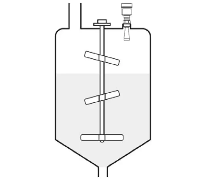
Figure – Radar Direct top vessel Installation
The sensor should be mounted perpendicular to the surface. The mounting socket on top of a vessel should be as short as possible.
In the case of instruments with horn antennas, the length of the socket should be less than the length of the horn antenna.
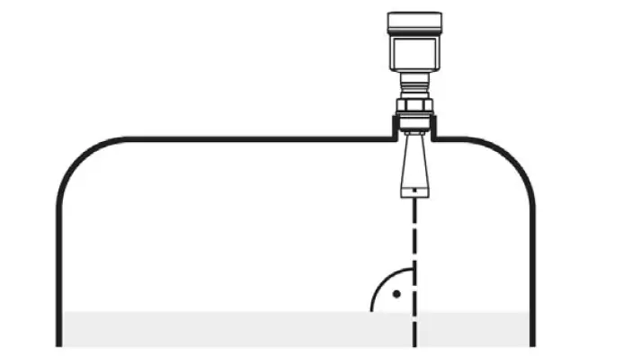
Figure – Radar alignment
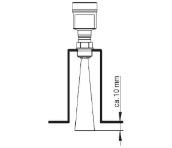
Figure – Radar socket or nozzle radar installation
If an access to the antenna is required (e.g. maintenance/operation) a full bore ball valve should be used.
Note: Electronic of non‐contact measurement are generally removable without a process shutdown.
This reduces the influence on the microwave and allows a reliable and accurate measurement.
Full bore valve is a solution if there is need to remove the cone antenna for maintenance (cleaning). Radar electronic can be changed without opening the tank.
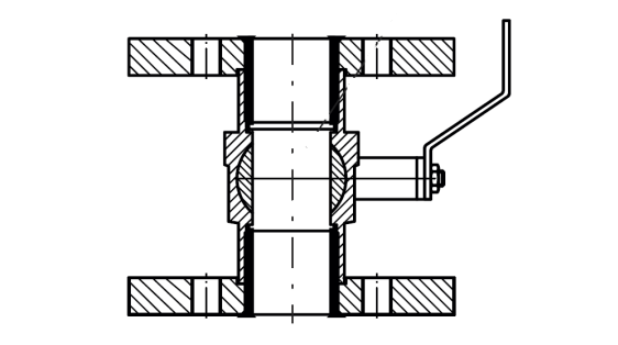
Figure – Radar full port ball valve
When installing a non‐contacting radar sensor on a stilling well or chamber/cage tube, the ID should minimum be the horn diameter.
Note: If the stilling well or chamber/cage ID is not constant, special parameter can be configured.
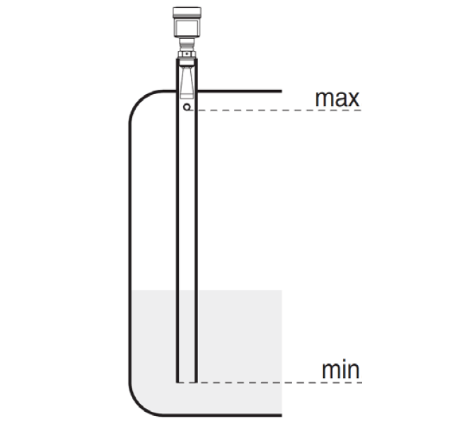
Figure – Radar installation using stilling well
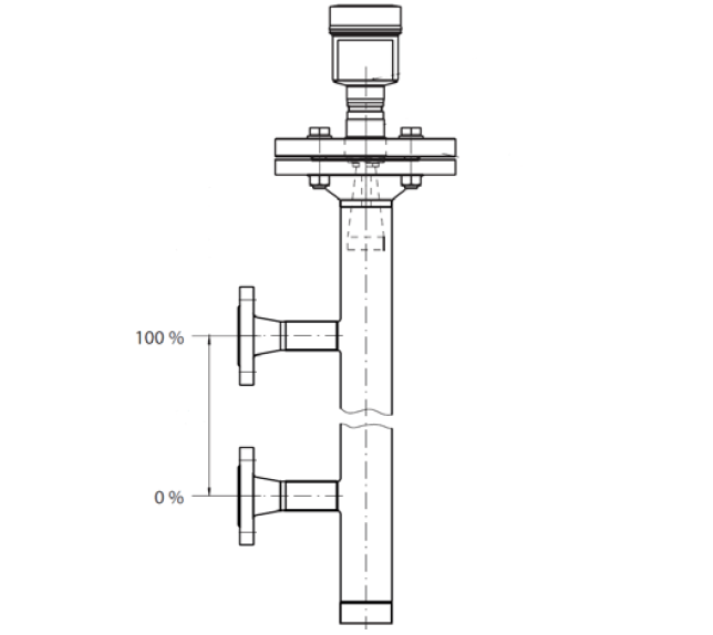
Figure – Radar installation using chamber/cage tube
For applications in insulated vessels, it is recommended to insulate also the nozzle, ball‐valve, flange and part of the instrument.
This prevents condensation and build‐up on the antenna and nozzle and increases the reliability and security for the measurement.
Floating Roof tanks
In some floating roof applications, it may be beneficial, or even the only way, to use the radar to measure to the floating roof instead of the liquid.
The sensor should be mounted perpendicular to the surface. In this application, the radar tracks the roof instead of the liquid.
An offset should be entered in the radar to allow for the roof thickness.
The radar will track the level down to where the roof leg lands. When the legs have landed, the radar will show the position of the roof even if the level is significantly lower.
The radar level accuracy is limited to how well the roof is following the liquid. There are seal frictions that influence how freely the roof is moving up and down. In some cases, the roof can stick during filling and emptying and that could result in measurement errors. If a lot of snow or water is collected on the roof, the radar gauge could start to measure to the snow/water instead of the roof.
If the radar is installed in an external floating roof tank the radar needs to have a Federal Communications Commission (FFC) license.
The radar gauge has an FCC part 15 license which is valid for a regular tank installation. In the external floating roof case, the radar gauge is in ‘open air’ and a FFC part 90; a license needs to be provided.
The application is straightforward and can be made online. This paragraph is pertinent for the installations located on the United States of America territory or where the USA regulations are mandatory and where FCC regulation applies.
The radar needs a horizontal reflector installed on the roof if the roof is not flat. This is normally the case for external floating roof tanks where the pontoon has a slight angle.
The reflector needs to be a minimum 50 mm × 50 mm (75 mm × 75 mm is generally used). The reflector should be installed in an area on the floating roof with as few metal obstructions as possible and horizontally mounted.
Calibration and configuration
Non‐contact Radars are initially calibrated in factory with an initial dielectric value (e.g. 1.6).
- Dry calibration: Zero and Full scale values are adjusted manually. These scale values represents the minimum and maximum level to be measured. These settings can be made in-situ or not.
- Wet calibration: wet calibration is necessary to take into account all the false echoes due to the internal vessel shape. The electronic record these false echoes. These false echoes are filtered and are no longer taken into account during the level measurement. This wet calibration should be performed with the actual low level so that all potential interfering reflections are detected.
Source : International Association of Oil & Gas Producers
Acknowledgements : IOGP Instrumentation and Automaton Standards Subcommittee (IASSC), BG Group, BP, Endress + Hauser, Emerson, Honeywell, Krohne, Petrobras, PETRONAS Carigali Sdn Bhd, Repsol, Siemens, Statoil, Total, Vega, Yokogawa.