History of the Modbus protocol
Some communication standards just emerge. Not because they are pushed by a large group of vendors or a special standards organisation.
These standards—like the Modbus interface—emerge because they are good, simple to implement and are therefore adapted by many manufacturers. Because of this, Modbus became the first widely accepted fieldbus standard.
Modbus has its roots in the late seventies of the previous century. It is 1979 when PLC manufacturer Modicon—now a brand of Schneider Electric’s Telemecanique—published the Modbus communication interface for a multidrop network based on a master/client architecture. Communication between the Modbus nodes was achieved with messages. It was an open standard that described the messaging structure.
The physical layer of the Modbus interface was free to choose. The original Modbus interface ran on RS-232, but most later Modbus implementations used RS-485 because it allowed longer distances, higher speeds and the possibility of a true multi-drop network.
In a short time hundreds of vendors implemented the Modbus messaging system in their devices and Modbus became the de facto standard for industrial communication networks.
The nice thing of the Modbus standard is the flexibility, but at the same time the easy implementation of it. Not only intelligent devices like microcontrollers, PLCs etc. are able to communicate with Modbus, also many intelligent sensors are equipped with a Modbus interface to send their data to host systems.
While Modbus was previously mainly used on wired serial communication lines, there are also extensions to the standard for wireless communications and TCP/IP networks.
Modbus
Modbus is one of the oldest fieldbuses on the market. It was developed in 1978 by the engineers at Modicon… originators of the first PLC. It’s primary purpose was, of course, to exchange data between PLCs and other devices on the production floor.
Since it is one of the oldest communication protocols it uses a more traditional approach to connecting devices. That approach is typically based upon a master/slave system over a serial line.(RS-232/485).
Depending upon which Modbus protocol is used, the communication can be either simple or peer-to-peer. The protocols available include ASCII/RTU or Modbus Plus. (Modbus/TCP is also available to talk on an ethernet line).
Modbus RTU messages, although simple, contain a 16-bit CRC (Cyclic-Redundant Checksum) to ensure reliability.
The simplicity of Modbus RTU messages is a mixed blessing; on the one hand, the simple message structure ensures widespread, rapid and accurate implementation, but on the other hand, various companies have corrupted the basic 16-bit Modbus RTU register structure to pack in floating point, queues, ASCII text, tables and other types of non-Modbus data.
Modbus RTU is an open, serial (RS-232 or RS-485) protocol based on master/slave or client/server architecture. It is popular, well established, relatively easy to implement and reliable.
Since it is so easy to implement, Modbus RTU has gained wide market acceptance wherever Industrial Automation Systems (IAS) or Building Management Systems (BMS) need to communicate with other devices. In fact, Modbus RTU is probably the most implemented automation protocol of all.
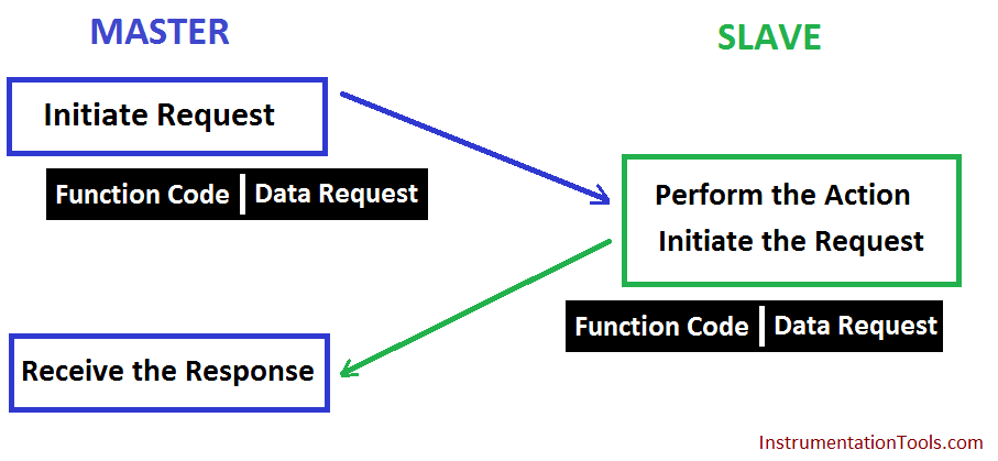
Modbus controllers use a master/slave communication method. This means that only one device (ie. the master) can initiate communication.
The other devices (ie. slaves) respond to the masters communication messages. They either send back the requested data or perform the requested operation.
The master can talk with individual slave units or all slave units at one time (ie. broadcast messages).
Regardless of the transmission ‘mode’ (ie. ASCII or RTU) the communication cycle and contents remains the same.
The frame of the message looks like this:
- Device Address
- Function Code
- 8-bit Data Bytes
- Error Checking
The master sends the above, the slave receives it and replies back in the same format. It’s important to note that the messages all have a known starting and ending point. This allows the receiving devices to know that a message has arrived, figure out if it’s for them or not, and know that the message has been completely received.
ASCII and RTU Modes
In ASCII/RTU modes (traditional Modbus) the user chooses either mode along with the serial port parameters (ie. baud rate, parity, etc).
These parameters must be the same for all devices on the Modbus network. Five wires is used for communication (#18AWG twisted pairs in a shielded jacket is generally recommended). Maximum transmission distance is 350m (1137ft).
ASCII mode: (American Standard Code for Information Interchange). This mode has an advantage of allowing up to 1 second time intervals to occur between character transmissions without generating an error. It’s most useful when communication is slow.
Two ASCII characters are sent as 8-bit data. A start and stop bit are also sent with each message creating a total of 10 bits. 7 data bits comprise the message and 1 bit is added for either even or odd parity. If no parity is used then the extra stop bit is added to maintain a total transmission of 10 bits.
It also uses LRC (Longitudinal Redundancy Check) to make sure what we sent is what we received.
RTU mode (Remote Terminal Unit). This mode has an advantage of sending more data in the same amount of time as in ASCII mode. Each message must be transmitted as a continuous stream of data, however.
Each 8-bit message will contain two 4 bit hex characters, thus sending the same amount of information in less space. Since we use an extra data-bit (8 vs 7) we send 11 bits in total. 8 data bits are used and 1 bit is used for either even or odd parity. If no parity is used, then an additional stop bit is added. This brings our total then to 11 bits (1 start + 8 data + 1 parity + 1 stop = 11 bits). This message uses CRC (Cyclical Redundancy Check) for error checking.
It is important to note that both ASCII and RTU modes use a master/slave configuration. This means that only a single device (ie. the master) can issue commands. The other devices (ie slaves) can only respond. The master can send messages to individual slaves or broadcast to all devices.
If peer-to-peer communication is required, an ‘upgrade’ to the later Modbus Plus is required. On this type of network, any device can initiate communication with any other device on the network. This adds many advantages in flexibility of communication.
However, even though it is peer-to-peer, on the message level it is master/slave. In other words, if a device asks another a question, it acts as a master and expects a reply from the other device which is acting as a slave.
Modbus Plus also allows us to interface with up to 32 devices at a total distance of 1500m (~4875ft). 3 repeaters may be used to get a total distance of 6000m (19,500ft) and 64 devices.
Modbus generally needs its own 12v supply to communicate and each device needs its own supply. In other words, the devices cannot be powered by the communications line.
ASCII message format
start(1 character) + address(2 characters) + function(2 characters) + data(x characters) + error check(2 characters) + ending(2 characters). In ASCII mode the start character is always a ‘:’ (ie. a colon, no quotes included).
The address field contains 2 characters. The valid slave device addresses are 0-247. The master addresses the proper slave device by putting the slave devices address in this field.
When the slave replies back it places its own address in this field so that the master knows which device has replied.
Address 0 is used as a broadcast address. In other words, all slaves will react to a message with an address of 0.
The function code also contains 2 characters. Valid function codes are 1-255. Some codes are product specific(to Modicon), others are universal, and still others are reserved for future use. The function code tells the slave device what to do.
Some examples of function codes include reading coil status, reading input status, reading memory locations, forcing coils on, writing to memory, etc.
The data field comes next and contains information that the slave devices will need to process the request from the master. For example, which coil statuses should be read, which coils should be forced on, etc.
The data field the slave sends back to the master will contain the data requested or an error code if there was an error. The error check field in ASCII mode contains the result of the LRC (Longitudinal Redundancy Check) calculation.
This calculation is simply done by adding together all the bytes in the message(excluding the start colon) eliminating any carries, and then 2’s complementing the result.
Lastly, the CR (carriage return) and LF (line feed) characters are added to the message. This tells the receiving device that the message has ended.
The RTU frames contain the same items except in a more compact form. Here is the message format: Start(4 character delay time) + address(8 bits) + function code(8 bits) + data(n x 8 bits) + error check(16 bits) + end (4 character delay time)
It is important to note that in ASCII mode there can be up to a 1 second delay between each character transmission but RTU mode can have a maximum of 1.5 character delay times between each character.
The only differences between ASCII and RTU message formats are the forming of the message, the start/ends, and the error checking.
The start/ends are simply 4 character time pauses. The error checking is CRC (Cyclical Redundancy Check) calculation.
Modbus Message Structure
The Modbus communication interface is built around messages. The format of these Modbus messages is independent of the type of physical interface used. On plain old RS232 are the same messages used as on Modbus/TCP over ethernet.
This gives the Modbus interface definition a very long lifetime. The same protocol can be used regardless of the connection type. Because of this, Modbus gives the possibility to easily upgrade the hardware structure of an industrial network, without the need for large changes in the software.
A device can also communicate with several Modbus nodes at once, even if they are connected with different interface types, without the need to use a different protocol for every connection.
On simple interfaces like RS485 or RS232, the Modbus messages are sent in plain form over the network. In this case the network is dedicated to Modbus.
When using more versatile network systems like TCP/IP over ethernet, the Modbus messages are embedded in packets with the format necessary for the physical interface.
In that case Modbus and other types of connections can co-exist at the same physical interface at the same time.
Although the main Modbus message structure is peer-to-peer, Modbus is able to function on both point-to-point and multidrop networks.
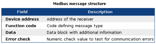
Each Modbus message has the same structure. Four basic elements are present in each message. The sequence of these elements is the same for all messages, to make it easy to parse the content of the Modbus message.
A conversation is always started by a master in the Modbus network. A Modbus master sends a message and—depending of the contents of the message—a slave takes action and responds to it. There can be more masters in a Modbus network.
Addressing in the message header is used to define which device should respond to a message. All other nodes on the Modbus network ignore the message if the address field doesn’t match their own address.
Modbus Serial Transmission Modes
Modbus/ASCII and Modbus/RTU
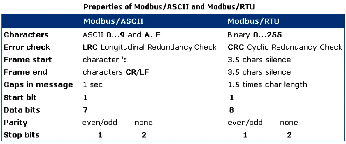
Serial Modbus connections can use two basic transmission modes, ASCII or RTU, remote terminal unit. The transmission mode in serial communications defines the way the Modbus messages are coded. With Modbus/ASCII, the messages are in a readable ASCII format.
The Modbus/RTU format uses binary coding which makes the message unreadable when monitoring, but reduces the size of each message which allows for more data exchange in the same time span.
All nodes on one Modbus network segment must use the same serial transmission mode. A device configured to use Modbus/ASCII cannot understand messages in Modbus/RTU and vice versa.
When using Modbus/ASCII, all messages are coded in hexadecimal values, represented with readable ASCII characters. Only the characters 0…9 and A…F are used for coding.
For every byte of information, two communication-bytes are needed, because every communication-byte can only define 4 bits in the hexadecimal system. With Modbus/RTU the data is exchanged in a binary format, where each byte of information is coded in one communication-byte.
Also Read : Modbus Questions & Answers
Modbus messages on serial connections are not sent in a plain format. They are framed to give receivers an easy way to detect the beginning and end of a message. When using Modbus/ASCII, characters are used to start and end a frame.
The colon ‘:’ is used to flag the start of a message and each message is ended with a CR/LF combination. Modbus/RTU on the other hand uses time gaps of silence on the communication line for the framing.
Each message must be preceded by a time gap with a minimum length of 3.5 characters. If a receiver detects a gap of at least 1.5 characters, it assumes that a new message is comming and the receive buffer is cleared.
The main advantage of Modbus/ASCII is, that it allowes gaps between the bytes of a message with a maximum length of 1 second. With Modbus/RTU it is necessary to send each message as a continuous stream.
Modbus Addressing
The first information in each Modbus message is the address of the receiver. This parameter contains one byte of information. In Modbus/ASCII it is coded with two hexadecimal characters, in Modbus/RTU one byte is used. Valid addresses are in the range 0..247.
The values 1..247 are assigned to individual Modbus devices and 0 is used as a broadcast address. Messages sent to the latter address will be accepted by all slaves.
A slave always responds to a Modbus message. When responding it uses the same address as the master in the request. In this way the master can see that the device is actually responding to the request.
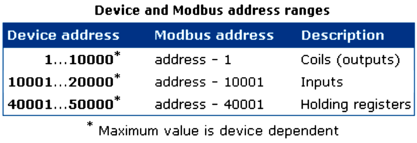
Within a Modbus device, the holding registers, inputs and outputs are assigned a number between 1 and 10000. One would expect, that the same addresses are used in the Modbus messages to read or set values. Unfortunately this is not the case.
In the Modbus messages addresses are used with a value between 0 and 9999. If you want to read the value of output (coil) 18 for example, you have to specify the value 17 in the Modbus query message.
More confusing is even, that for input and holding registers an offset must be substracted from the device address to get the proper address to put in the Modbus message structure. This leads to common mistakes and should be taken care of when designing applications with Modbus.
The following table shows the address ranges for coils, inputs and holding registers and the way the address in the Modbus message is calculated given the actual address of the item in the slave device.
Modbus Function Codes
The second parameter in each Modbus message is the function code. This defines the message type and the type of action required by the slave. The parameter contains one byte of information.
In Modbus/ASCII this is coded with two hexadecimal characters, in Modbus/RTU one byte is used. Valid function codes are in the range 1..255.
Not all Modbus devices recognize the same set of function codes. The most common codes are discussed here.
Normally, when a Modbus slave answers a response, it uses the same function code as in the request.
However, when an error is detected, the highest bit of the function code is turned on. In that way the master can see the difference between success and failure responses.
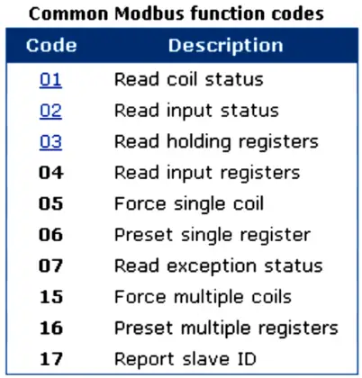
Function 01: Read coil status
In Modbus language, a coil is a discrete output value. Modbus function 01 can be used to read the status of such an output. It is only possible to query one device at a time. Broadcast addressing is not supported with this Modbus function.
The function can be used to request the status of various coils at once. This is done by defining an output range in the data field of the message.
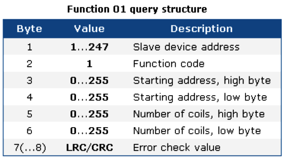
When receiving a Modbus query message with function 01, the slave collects the necessary output values and constructs an answer message.
The length of this message is dependent on the number of values that have to be returned. In general, when N values are requested, a number of ((N+7) mod 8) bytes are necessary to store these values.
The actual number of databytes in the datablock is put in the first byte of the data field. Therefore the general structure of an answer to a Modbus function 01 query is:
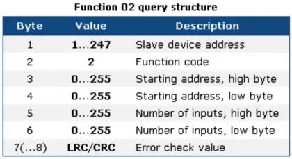
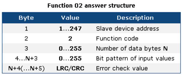
After receiving a query message with Modbus function 02, the slave puts the requested input values in a message structure and sends this message back to the Modbus master.
The length of the message depends on the number of input values returned. This causes the length of the output message to vary.
The number of databytes in the data field that contain the input values is passed as the first byte in the data field.
Each Modbus answering message has the following general structure.
Function 03: Read holding registers
Internal values in a Modbus device are stored in holding registers. These registers are two bytes wide and can be used for various purposes.
Some registers contain configuration parameters where others are used to return measured values (temperatures etc.) to a host.
Registers in a Modbus compatible device start counting at 40001. They are addressed in the Modbus message structure with addresses starting at 0.
Modbus function 03 is used to request one or more holding register values from a device.
Only one slave device can be addressed in a single query. Broadcast queries with function 03 are not supported.
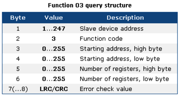
After processing the query, the Modbus slave returns the 16 bit values of the requested holding registers.
Because of the size of the holding registers, every register is coded with two bytes in the answering message.
The first data byte contains the high byte, and the second the low byte of the register.
The Modbus answer message starts with the slave device address and the function code 03.
The next byte is the number of data bytes that follow. This value is two times the number of registers returned.
An error check is appended for the host to check if a communication error occured.
Also Download : Modbus Softwares
Details of ASCII and RTU mode message formats
ASCII message format:
start(1 character) + address(2 characters) + function(2 characters) + data(x characters) + error check(2 characters) + ending(2 characters)
In ASCII mode the start character is always a ‘:’ (ie. a colon, no quotes included).
The address field contains 2 characters. The valid slave device addresses are 0-247. The master addresses the proper slave device by putting the slave devices address in this field.
When the slave replies back it places its own address in this field so that the master knows which device has replied. Address 0 is used as a broadcast address.
In other words, all slaves will react to a message with an address of 0.
The function code also contains 2 characters. Valid function codes are 1-255. Some codes are product specific to Modicon, others are universal, and still others are reserved for future use.
The function code tells the slave device what to do. Some examples of function codes include reading coil status, reading input status, reading memory locations, forcing coils on, writing to memory, etc.
The data field comes next and contains information that the slave devices will need to process the request from the master.
For example, which coil statuses should be read, which coils should be forced on, etc. The data field the slave sends back to the master will contain the data requested or an error code if there was an error.
The error check field in ASCII mode contains the result of the LRC (Longitudinal Redundancy Check) calculation.
This calculation is simply done by adding together all the bytes in the message (excluding the start colon) eliminating any carries, and then 2’s complementing the result.
Lastly, the CR (carriage return) and LF (line feed) characters are added to the message. This tells the receiving device that the message has ended.
The RTU frames contain the same items except in a more compact form.
Here is the message format:
Start(4 character delay time) + address(8 bits) + function code(8 bits) + data(n x 8 bits) + error check(16 bits) + end (4 character delay time)
It is important to note that in ASCII mode there can be up to a 1 second delay between each character transmission but RTU mode can have a maximum of 1.5 character delay times between each character.
The only differences between ASCII and RTU message formats are the forming of the message, the start/ends, and the error checking.
The start/ends are simply 4 character time pauses. The error checking is CRC (Cyclical Redundancy Check) calculation.
Modbus Protocol versions
Versions of the Modbus protocol exist for serial port and for Ethernet and other protocols that support the Internet protocol suite.
There are many variants of Modbus protocols:
- Modbus RTU — This is used in serial communication and makes use of a compact, binary representation of the data for protocol communication. The RTU format follows the commands/data with a cyclic redundancy check checksum as an error check mechanism to ensure the reliability of data. Modbus RTU is the most common implementation available for Modbus. A Modbus RTU message must be transmitted continuously without inter-character hesitations. Modbus messages are framed (separated) by idle (silent) periods.
- Modbus ASCII — This is used in serial communication and makes use of ASCII characters for protocol communication. The ASCII format uses a longitudinal redundancy check checksum. Modbus ASCII messages are framed by leading colon (“:”) and trailing newline (CR/LF).
- Modbus TCP/IP or Modbus TCP — This is a Modbus variant used for communications over TCP/IP networks, connecting over port 502. It does not require a checksum calculation, as lower layers already provide checksum protection.
- Modbus over TCP/IP or Modbus over TCP or Modbus RTU/IP — This is a Modbus variant that differs from Modbus TCP in that a checksum is included in the payload as with Modbus RTU.
- Modbus over UDP — Some have experimented with using Modbus over UDP on IP networks, which removes the overheads required for TCP
- Modbus Plus (Modbus+, MB+ or MBP) — Modbus Plus is proprietary to Schneider Electric and unlike the other variants, it supports peer-to-peercommunications between multiple masters. It requires a dedicated co-processor to handle fast token rotation. It uses twisted pair at 1 Mbit/s and includes transformer isolation at each node, which makes it transition/edge-triggered instead of voltage/level-triggered.
- Pemex Modbus — This is an extension of standard Modbus with support for historical and flow data. It was designed for the Pemex oil and gas company for use in process control and never gained widespread adoption.
- Enron Modbus — This is another extension of standard Modbus developed by Enron Corporation with support for 32-bit integer and floating-point variables and historical and flow data. Data types are mapped using standard addresses. The historical data serves to meet an American Petroleum Institute (API) industry standard for how data should be stored.
Data model and function calls are identical for the first 4 variants of protocols; only the encapsulation is different.
However the variants are not interoperable, nor are the frame formats.
Awesome explanation. Thank You for sharing complete knowledge.