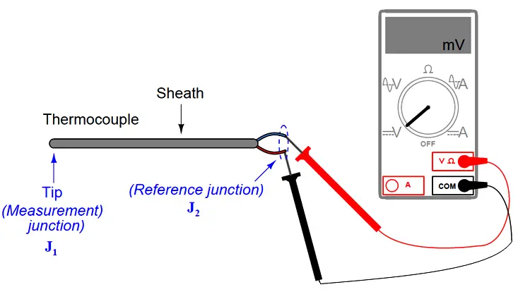
The amount of voltage indicated by a voltmeter connected to a thermocouple is the difference between the voltage produced by the measurement junction (the point where the two dissimilar metals join at the location we desire to sense temperature at) and the voltage produced by the reference junction (the point where the thermocouple wires join to the voltmeter wires):

Vmeter = VJ1 − VJ2
This makes thermocouples inherently differential sensing devices: they generate a measurable voltage in proportion to the difference in temperature between two locations. This inescapable fact of thermocouple circuits complicates the task of interpreting any voltage measurement obtained from a thermocouple. In order to translate a voltage measurement produced by a voltmeter connected to a thermocouple, we must add the voltage produced by the measurement junction (VJ2) to the voltage indicated by the voltmeter to find the voltage being produced by the measurement junction (VJ1). In other words, we manipulate the previous equation into the following form:
VJ1 = VJ2 + Vmeter
We may ascertain the reference junction voltage by placing a thermometer near that junction (where the thermocouple wire attaches to the voltmeter test leads) and referencing a thermocouple table showing temperatures and corresponding voltages for that thermocouple type. Then, we may take the voltage sum for VJ1 and re-reference that same table, finding the temperature value corresponding to the calculated measurement junction voltage. The National Institute of Standards and Technology (NIST) in the United States publishes tables showing junction voltages and temperatures for standardized thermocouple types. While it is possible to mathematically model a thermocouple junction’s voltage in the same way we may model an RTD’s resistance, the functions for thermocouples are less linear than for RTDs, and so tables are greatly preferred for practical use.
Also Check : Thermocouple Tables
To illustrate, suppose we connected a voltmeter to a type K thermocouple and measured 14.30 millivolts. A thermometer situated near the thermocouple wire / voltmeter junction point shows an ambient temperature of 73 degrees Fahrenheit. Referencing a table of voltages for type K thermocouples (in this case, the NIST “ITS-90” reference standard), we see that a type K junction at 73 degrees Fahrenheit corresponds to 0.910 millivolts. Adding this figure to our meter measurement of 14.30 millivolts, we arrive at a sum of 15.21 millivolts for the measurement (“hot”) junction. Going back to the same table of values, we see 15.21 millivolts falls between 701 and 702 degrees Fahrenheit. Linearly interpolating between the table values (15.203 mV at 701 oF and 15.226 mV at 702 oF), we may more precisely determine the measurement junction to be 701.3 degrees Fahrenheit.
The process of manually taking voltage measurements, referencing a table of millivoltage values, performing addition, then re-referencing the same table is rather tedious. Compensation for the reference junction’s inevitable presence in the thermocouple circuit is something we must do, but it is not something that must always be done by a human being. The next subsection discusses ways to automatically compensate for the effect of the reference junction, which is the only practical alternative for continuous thermocouple-based temperature instruments.
Also Check : Thermocouple Calculator
Credits : Tony R. Kuphaldt – Creative Commons Attribution 4.0 License